Tsmp Mould - Produits, offres, nouvelles
Actualités
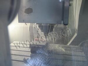
High speed machining for die and mould industry
2011.11.07
Developed for high accuracy, up to 40,000 revs/min, three-axis, simultaneous 3-D profiling, the OPS high speed vertical machining centre is very compact, stable and cost-effective
Developed for high accuracy, up to 40,000 revs/min, three-axis, simultaneous 3-D profiling, as well as conventional machining in materials as diverse as graphite, plastics, copper, soft and hardened steels, the OPS high speed vertical machining centre is very compact, stable and cost-effectively priced.
Available from Traub Heckert UK of Brackley in Northamptonshire, the OPS machine can be specified in two versions.
The OPS 400 has axis travels of 400 mm by 210 mm by 200 mm with a maximum table loading of 200 kg and the larger OPS 600 variant, 600 mm by 375 mm by 350 mm with table loading of 800 kg.
Overall foot print dimensions of each machine are small at 1.1 m by 1.5 m by 1.9 m and 1.6 m by 2.0 m by 2.2 m respectively.
Built upon a polymer concrete base, the machine has high rigidity and excellent vibration absorption capability.
High accuracy linear guideways with fully integrated and sealed lubrication, provide virtually maintenance-free operation even when machining graphite materials.
Axis drives are via digital AC motors giving feed rates up to 20 m/min with acceleration of 8 m/sec2.
Repeatable accuracy is 0.002 mm.
A high frequency spindle with 9 kW drive and HSK-32E taper has a speed range between 5,000 and 40,000 revs/min.
The spindle is supplied via a 12-station, machine base mounted, disc tool changer.
Options for 24 or 30 position magazines are available for sister tool replacement, extensive multi-feature type components or longer uninterrupted machining cycles.
These machining requirements can also be supplemented via a workpiece changer providing up to 60 component positions.
Control is through a Windows NT PC-based unit with dual processor technology providing 'unlimited' look ahead.
On-machine programming or 1S0 compatible program format supports all common CAD/CAM systems.
Temperature compensation is included along with integrated tool management software.
Options include a rotational fourth axis.
Oil mist lubrication can be supplied to suit customer preference against the standard dry cutting machine design.
The guarding is hermetically sealed and a powerful vacuum system incorporated, which also restricts noise generation from the cutting zone.
U.S. extruder builds manufacturing plant in Hangzhou.
2011.11.07
Steve Toloken
HANGZHOU, CHINA — Spurred by rapidly growing demand in China’s healthcare market, American specialty tubing extruder Precision Extrusion Inc. has opened a joint venture manufacturing plant in the eastern Chinese city of Hangzhou.
Precision, in Glens Falls, N.Y., has seen China grow from negligible sales levels five years ago to about 20 percent of the small company’s revenues, as the Chinese government has significantly boosted spending on healthcare, said Precision President Michael Badera, speaking in an April 16 interview at the China International Medical Equipment Fair, in Shenzhen, China.
Precision has a majority stake, while a Chinese investment firm Tong Xiang Peng Yi Ltd., in the city of Tongxiang, Zhejiang province, holds a minority position, he said, declining to disclose details of the investment or ownership stakes.
“It was a multimillion dollar investment,” Badera said.
The joint venture, which started production earlier this year, is called Hangzhou Peng Yi Precision Catheter Technology Ltd. The Chinese partner is a small privately-owned investment firm, Badera said.
The Hangzhou facility could eventually start to manufacture some of the company’s catheter balloons and have operations for applying lubricious coatings, which make the catheters easier to insert into the body, he said.
The factory is in the Hangzhou Economic and Technology Development Area, a giant industrial park outside the city. The park was helpful to Precision and provided the firm some grants to help defray rental costs, he said.
Badera also said the joint venture is considering expanding beyond components into producing finished goods and eventually doing an initial public offering.
Precision Vice President Rosy Wang, a native of Hangzhou and longtime employee of Precision, is the chairman of the joint venture.
Mold Base
2011.08.24
Mold base is a comprehensive name used for the parts for containing the cavity for plastic injection mold, and also has the role of directly installing the mold to the plastic injection molding machine.
Mold base is a set of parts that constitute the outer periphery part of a plastic injection mold, and is constituted mainly from the following parts.
(1) Fixed half retainer plate
(2) Fixed half mold plate
(3) Moving half mold plate
(4) Spacer blocks
(5) Ejector plate (top)
(6) Ejector plate (bottom)
(7) Moving half retainer plate
(8) Runner stripper plates (in the case of a 3-plate structure)
Although previously the constituent parts of a mold base were all designed and manufactured as required, standard mold bases have recently come into wider use and are being used all over the world. In the case of large sized molds or small sized molds, even at present, they are being designed individually for each mold.
Although the standards for mold bases have been prepared in Japan in metric units, they are still being prepared in inch units in the U.S.A. In Europe, as in Japan, it is common to prepare them in metric units.
The following two types of structures are the most commonly used ones for the structure of a mold base.
(1) 2-plates structure
(2) 3-plates structure
The selection between these two structures is determined by the method of the gate used. When adopting a pin point gate structure, always the structure (2) is used. In the case of a side gate or a tunnel gate, the structure (1) is used normally.
The material for the constituent parts of the mold base is generally the carbon steel for machine construction (S55C, 220C, etc.,) and is used most often in the non-hardened condition. In special applications, pre-hardened steel, or stainless steel, or an aluminum alloy is used some times. A mold based used in combination with accessory parts like guide pins, guide bushes, return pins, etc.
Basic Varieties of Tunnel Gates
2011.08.24
A tunnel gate (submarine gate) is used very frequently as a gate method for a structure that automatically cuts the product and the gate at the time of opening and closing the parting surface.
While the know how of the shape and dimensions, etc., is necessary at the time of the basic design of a tunnel gate, here, the basic varieties in the relationships among the product, the gate, and the runner are explained.
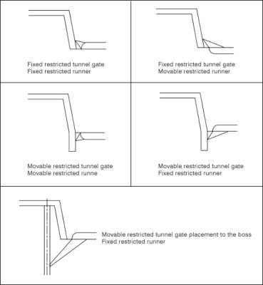
The basic patterns of tunnel gates generally used are shown in the following figure. When these are broadly classified into a movable side and a fixed side with the parting surface in between them, there are four types of combinations of the gate and runner.
When the tunnel gate is provided on the fixed side, cutting of the molded product and the gate is done at the time when the parting surface is opened. Therefore, the condition of gate cutting is considered to vary depending on the speed of opening the mold.
On the other hand, when the tunnel gate is provided on the fixed side, the cutting of the molded product and gate is done at the time when the runner ejector pin protrudes from the runner. Therefore, the condition of gate cutting is considered to vary depending on the speed of the protruding runner ejector pin.
When the runner is provided on the fixed side, since it is likely that the runner itself remains on the fixed side, it is necessary to have a structure with a long pin in which case the runner is pulled to the movable side.
When the runner is provided on the movable side, it is necessary to provide an appropriate ejector pin for protruding the runner.
As a special example, there is a structure in which the tunnel gate is provided on a boss shape (formed by fine grinding the ejector pin) located on the movable side, and the plastic is injected from the underside of the top surface of the molded product.
In actuality, depending on the features of the molded product or the characteristics of the plastic, the design of the mold is carried out considering which gate pattern and which runner pattern is most appropriate.
Selection of the Runner Cross-sectional Shape
2011.08.24
The runner is a path for making the molten plastic flow from the sprue to the molded product. The cross-sectional shape of the runner is selected depending on the size of the molded product, the type of plastic, the estimated molding conditions, etc.
The basic standards for selecting the runner cross-sectional shape are explained here.
The figure below shows some typical runner cross-sectional shapes.
The runner is selected from the following three types.
1)The type carved on the moving half
2)The type carved on the fixed half
3)The type carved on both the fixed half and the moving half.
The selection among these is made appropriately based on the restrictions imposed by the shape of the molded product, the mold parting position, etc.
The most important role of the runner is to make the molten plastic flow in a condition in which no pressure loss is present. An unnecessarily large volume runner has the bad effects of increasing the scrap, worsening the material cost, lengthening the molding cycle, increasing the waste material, etc.
An index of the efficiency of a runner is the diameter and area of the inscribed circle in the cross-sectional shape. If the area of the inscribed circle increases, the area for hot plastic to flow becomes wide, and hence the molten plastic can flow easily.
Consequently, a runner with a circular cross section is the most ideal one. However, since it will be necessary to carve the runner in both the fixed side and the movable side, the cost of manufacturing the mold increases. In order to solve these problems, a rectangular cross-sectional shape runner or a runner with a semicircular cross-sectional shape that is made still deeper is used.
It is desirable to provide an angle at the side surface of the runner for separating from the mold. In addition, the inner surface of the runner is polished to a smooth surface using a rubber grinder or by carrying out lapping, thereby preventing pressure loss.
Designing the Tip Shape of Pin Point Gate
2011.08.24
The problems that can occur in the case of pin point gate structure are the following.
1) The tip of the gate remains as a projection on the surface of the molded product, or scratches out a part of the molded product.
2) The filling does not progress smoothly in spite of the filling pressure or the dwell pressure being high.
These are the problems that a mold designer has to solve whenever adopting a pin point gate.
Some technical measures for solving these problems are described below.
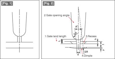
Fig. 1 shows the structure of a general pin point gate. This is the shape when the gate design is made without any special considerations.
On the other hand, Fig. 2 is a design in which measures have been taken to solve the above problems.
The problems that can occur in the case of pin point gate structure are the following.
1) The tip of the gate remains as a projection on the surface of the molded product, or scratches out a part of the molded product.
2) The filling does not progress smoothly in spite of the filling pressure or the dwell pressure being high.
These are the problems that a mold designer has to solve whenever adopting a pin point gate.
Some technical measures for solving these problems are described below.
Fig. 1 shows the structure of a general pin point gate. This is the shape when the gate design is made without any special considerations.
On the other hand, Fig. 2 is a design in which measures have been taken to solve the above problems.
Key factor 1: Gate land length L
If the gate land length is longer than necessary, at the time of cutting the gate part, it is possible that the gate gets cut in the middle thereby leaving a projection on the molded product.
As a rule of experience, it is recommended that the gate land length L is in the range of about 1 to 2 times the gate tip diameter d.
Key factor 2: Gate opening angle A
As an opening angle, a gate is provided with a conical shaped taper. If it has a conical shape, at the time of cutting the gate, the possibility becomes high that the gate is always cut at the minimum cross-section part where the gate and the molded product meet.
In addition, even releasing from the mold becomes easier. Generally, the value of A is about 15 to 30. Although the cutting becomes definite when the value is large, there is also a trend that the wear of the tip part progresses faster.
Key factor 3: Recess
If the gate is made to penetrate more into the molded product by forming a recess at the surface where the gate meets the molded product, even if there is a projection at the cut part, it will not project beyond the surface of the molded product.
For providing a recess, it is always necessary to get the permission in the drawing for the change in the specifications from the designer of the molded product.
Key factor 4: Dimple
A dimple is a spherical shaped depression provided on the side opposite the gate of the same extent as the ordinary wall thickness of the molded product so that the molten plastic can flow in a stable manner.
Even for providing a dimple, it is always necessary to get the permission in the drawing for the change in the specifications from the designer of the molded product.
In the above manner, if considerations are given in the design aspects, and also, if the gate has been machined accurately using electric discharge machining, etc., there is a very high probability that the above problems are solved.
Molding Shrinkage Ratios of Major Plastic Materials
2011.08.24
In order to carry out the design of molds for plastic injection molding, it is necessary to determine the molding shrinkage ratio. In this course, rough guides of the molding shrinkage ratios are explained for the typical plastic materials used in injection molding.
this is a list of the major thermoplastic materials, their molding shrinkage ratios, cavity surface temperatures, and injection molding pressures.
For more details, it is common practice to obtain the material catalogs and technical documents for each grade from the manufacturers of the molding materials and to use them as the reference materials for making decisions.
Basic Theory of Molding Shrinkage Ratio
2011.08.24
Molding shrinkage ratio is one of the most important factors in the design of molds for plastic injection molding.
The molding shrinkage ratio α can be expressed by the following equation.
α=(L0-L)/L0, where,
α:Molding shrinkage ratio (no units)
L0:Mold dimensions (mm)
L:Product dimensions(mm)
However, in actuality, since the volume shrinks when the molten plastic cools, if the concept of volume shrinkage ratio is used, it can be expressed by the following equation.
αv=(V0-V1)/V0, where,
αv:Volume shrinkage ratio (no units)
V0:Volume of the mold cavity(mm3)
V1:Volume of the molded product(mm3)
Here, if the volumes V0 and V1 are considered as three dimensional objects, it is possible to express them using the following equations.
L0=3√V0
L1=3√V1
Therefore,
αv=(V0-V1)/V0
=1-(V1/V0)1/3
=1-(v1/v0)1/3 , where,
v1:Specific volume at room temperature (mm3/g)
v0:Specific volume under molding conditions (mm3/g)
In addition, it is known that the state equation of the molten plastic can be expressed as follows.
(P+πi)(v-ω)=R'T, where,
v:Specific volume of the molten plastic(mm3/g)
πi:Internal pressure (atm)
ω:Specific volume at absolute zero degrees(mm3/g)
R':R/M(Corrected gas constant atm mm3/g・mol)
M:Molecular weight in units of molecular activity
If αv =1-(v1/v0)1/3 is substituted in the above equation, we get:
α=1-3√y
=(1-y)/3+(1-y)2/9
y=v0(P+πi)/R'T+ω(P+πi)
From this, it is also clear theoretically that the Pressure P and the temperature T of the molten plastic have a large influence on the molding shrinkage ratio α.
Hot Runner Technology
2011.08.24
A hot runner has the feature that it is possible to carry out injection molding without generating runner parts such as scrap, etc., by incorporating an electrically heated runner part in the mold.
Since hot runners make it possible to make the amount of scrap generated during the large scale manufacturing of plastic injection molded products extremely small, hot runners are a technology that make it possible to achieve great reductions in the cost of scrap processing. In addition, since the filling pressure loss that occurs in the case of cold runners becomes small in the case of hot runners, it is possible to suppress a fall in the filling pressure. Further, it is also possible to aim at shortening the cooling cycle. Hot runners have been used in Japan in a large number of cases, such as for the production of food containers, medical implements, automotive parts, etc.
Hot runner systems are broadly classified into those in which the mechanism part is a manifold part and those in which the mechanism part is a nozzle part. In addition, a controller is also required for carrying out the temperature control of the hot runner part.
Hot runners can be designed and built in-house within the company, or can be purchased from outside as systems. In general, the method of purchasing and applying a system available in the market is used most often. About 20 Japanese and foreign companies are supplying such systems to the market, and all of them have their own technical features for the method of heating or for the heat transmission structure. For example, the external heating method or the internal heating method can be used as the nozzle heating method. Further, various valve gate structures have been developed, such as the one in which the gate is opened and closed mechanically by force.
Since there are different types of hot runners that are used depending on the material to be molded and since molding is difficult in the case of some hot runners, it is necessary to sufficiently study in advance the type of plastic and the presence or absence of glass fibers, etc. During the design of the mold, it is necessary to propose the structure for incorporating a hot runner or manifold, the countermeasures against thermal expansion, the cooling structure, the maintenance structure, etc. The design is different from that of an ordinary mold, and it is necessary to thoroughly investigate the thermal calculations and the strength calculations. In addition, since recovering the initial investment for hot runners is difficult unless the production quantity of the molded product is large, it is necessary to verify the plan in detail as to how much planned production is to be made using that mold. In recent times, a trend can be seen in using valve gates or new types of hot runners in the development of molded products of super engineering plastics whose material costs are high. Even in Japan this technology is being considered to be used more and more frequently in the future as a means for making the costs of molding materials a minimum and for realizing molding that is in harmony with the environment.
Appropriate Pre-drying of Plastic Molding Materials (Revised Version)
2011.08.24
Usually, the plastic materials are formed in the shape of pellets and sent from the raw material manufacturers in paper bags, etc.
Since these pellets would have absorbed the moisture in the atmosphere, if they are used for injection molding while they still contain a lot of moisture, depending on the type of material, they can undergo hydrolysis, or their physical properties can decrease. Further, it is possible for silver streaks to appear on the surface of the molded product, and it is also possible for short shots or burn due to gas to occur.
In view of this, in the case of most molding materials, before they are put into the hopper drier, it is necessary to carry out pre-drying in a box type drying oven.
In pre-drying it is recommended to observe the appropriate drying temperature and drying time. This is because, if the drying is done at a temperature less than the appropriate temperature, even if the drying is done for a long time, the moisture content cannot be removed as desired. A material whose pre-drying has been completed should be used as quickly as possible. When any left over material is to be used some days later, carry out its pre-drying again before use.
Pellets of plastic molding materials generally absorb moisture from the atmosphere to a certain extent. If the quantity of absorbed moisture is large, the plastic can undergo hydrolysis (there are plastics that undergo chemical dissociation with water as the initiator) in the process of being melted and mixed in the cylinder of the injection molding machine, or, when molding is done, this can cause silver streaks, air bubbles, or glossiness defects on the surface of the molded product, or can cause copying defects, etc. Therefore, it is necessary beforehand to put the pellets of molding materials in a drying apparatus and remove the moisture content in them. If the pre-drying is not done appropriately, it can lead to variations in the fluidity, deterioration of physical characteristics, and molding defects.
(1) Hot air drier
The hopper drier and the box type drier are the typical equipment used with this type. The drying method is that of blowing hot air at the pellets thereby evaporating the moisture in them. Although this is a common and simple drying method, this method is not suitable for completely removing the moisture content.
(2) Dehumidified hot air t drier
In this method, after first removing the moisture in air, that air is heated and blown on the pellets thereby evaporating the moisture content in them. Since the air used for drying is re-circulated and used again after being dehumidified, heat loss will be small, and it is possible to carry out rational drying. This method is suitable for drying PBT, etc.
(3) Reduced pressure heat transfer type drier
This is a method for evaporating the moisture content in the pellet by heat transfer in a reduced pressure environment. Drying at low temperatures becomes possible, and hence it is possible to prevent the oxidization of plastic and to reduce the effects of additives in the pellet. In addition, this is also a method in which thermal loss is also small. This type of drier is attracting a lot of attention as the drier of the future.
Haas Opens First HFO in North Africa
2011.08.18
The first Factory Outlet in North Africa is a step toward Haas Automation’s objective of capturing a substantial share of the regional market for CNC machine tools.
On June 10, the CNC machine tool manufacturer Haas Automation Europe opened the first Haas Factory Outlet (HFO) to be situated in North Africa. More than 80 people attended the grand opening event. The new HFO in Casablanca, Morocco, is owned and managed by a well-established French HFO, Performer CNC.
Performer CNC is working in partnership with Technique Acier, a Casablanca-based organization that has many years of experience in the precision engineering sector.
Alain Reynvoet, managing director for Haas Automation Europe, sees great potential in Morocco and the region. “The country is improving its infrastructure, and foreign companies, including several well-known car manufacturers, are investing in local production plants,” he explains. “This is the perfect time for us to enter the growing North Africa market, and we are pleased to be doing so in Morocco with our partner Performer CNC, a company that has an intimate understanding of both the business culture in this region and also of Haas CNC machine tools.”
Haas Automation may well be the first CNC machine tool company to open a dedicated sales and service facility in Morocco. Usually, in countries where Haas has been the first to invest, the company has subsequently enjoyed a consistent 40% share as the market develops.
“We’re aiming for at least 25%,” says Reynvoet, “and since we have many new, improved products developed over the last two years, we’re confident we’ll enjoy an even greater share. Our target for the first year is to supply at least 20 Haas machines and to provide customers with a level of service and support that has been missing here for many years.”
Haas Automation Europe’s marketing director Katja Mader also attended the grand opening in Casablanca. “Given the amount of investment taking place in the country—in the transport infrastructure, business and industry, et cetera—Morocco is the best place in the Maghreb countries for us to begin local sales in North Africa,” she explains. “But, when we find the right partners, we also aim to establish HFOs as soon as possible in Algeria and Tunisia.”
AfriMold Conference Draws Top International Speakers
2011.08.18
South Africa’s second international trade fair focused on mould making, tooling, design, and application development, AfriMold 2011, has gathered major momentum, with the three-day conference running alongside the exhibition now promising more than 40 papers to be delivered by leading local and international industry experts.
The event, organized by DEMAT GmbH, takes place September 27–29 at the Sandton Convention Centre in the South African capital of Johannesburg. The Toolmaking Association of South Africa (TASA) also has prominence at AfriMold, in that it serves as conference sponsor and is the driving force behind initiatives aimed at significantly increasing the number of students and apprentices being trained and becoming involved in the industry.
“The response to the Tooling Technologies 2011 and Beyond conference has been way beyond our initial expectations,” says exhibition managing director Ron MacLarty. “We have received abstracts that confirm that the conference will deal with important industry issues while also underlining the progress achieved by the industry both locally and overseas using the latest in manufacturing technologies.”
Speakers include senior representatives from German institutions such as the Fraunhofer Institute for Laser Technology and RWTH Aachen University. Local institutions participating in the conference include the Central University of Technology Free State, the Vaal University of Technology, the Institute for Advanced Tooling within the Department of Industrial Engineering at Stellenbosch University, and the National Laser Centre of the CSIR.
Papers will cover such topics as industry training, the South African tooling sector and international competitiveness, micro- and nanostructuring of tools with lasers, laser applications in tool and mould making, automated mould polishing, hybrid tooling approaches to injection moulding, 5-axis machining in the toolroom, and others.
“The conference presents a new dimension of the exhibition, with a good mix of papers,” declares MacLarty. “It will provide a platform for the expression of new thinking in terms of theory and design that will lead machinery and production in new directions through the expansion and extension of existing theories and the roles played by the machinery on the shop floor.”
The AfriMold MD continues: “We have excellent overseas participation and representation to enrich the experience for the local industry, which will benefit from knowledge exchange and gain a benchmark for the type of machinery they need, as well as an understanding of where the industry is headed both locally and internationally.”
Italian Machine Tool Orders Continue Upward Trend
2011.08.18
In the second quarter of 2011, orders placed for Italian machine tools were up 13% over the same period last year, continuing a positive trend. The absolute value of the index of orders, 90.1 (against the 2005 base of 100), approaches pre–economic crisis levels. The data are from the Studies Department of UCIMU-Sistemi per Produrre.
The association of Italian machine tools, robots and automation manufacturers explains that the year-on-year second-quarter increase in orders was due entirely to excellent foreign demand. The index of orders placed in foreign markets increased by 44.5% over the period of April–June 2010, for an absolute value of 102.
The domestic market, on the other hand, did not take Italian manufacturers up on their offer. Domestic orders fell from Q2 2010 to Q2 2011 by 33.8%, resulting in an absolute index value of 59.2.
On a six-month basis, the increase in order intake this year amounted to 16.3% (for an absolute value of 101.5) over the period of January to June 2010, thanks to foreign orders rising by 37.4%, which more than balanced out the 19.5% decrease in internal orders.
“The quarterly survey which extends the positive streak recorded from the start of 2010 is certainly comforting,” says Giancarlo Losma, president of UCIMU-Sistemi per Produrre. “Our factories have now begun to return to productivity levels close to those reached previous to the crisis.”
What continues to worry Losma is the constantly widening sizable gap between orders received from domestic manufacturers and those from foreign markets. This trend looks irreversible, he says, attributing it to not only weakness in domestic demand but also to the decision of Italian manufacturers to favour marketing their products abroad.
“We are witnessing, in essence, a clear shift of our businesses toward those areas that appear more interesting in terms of profitable business activity and appreciation of our supply,” Losma continues. “Due to this, the decision to remove ICE, the Italian Institute for Foreign Trade, seems to be short-sighted, because, although requiring clear reorganization, it was the right tool to support the internationalization of Italian businesses.”
While Italian equipment manufacturers are looking toward more-active markets overseas, foreign competitors are gaining an advantage in the Italian market by selling standardized machines of medium quality at “reasonable” prices, explains Losma. “These trends denote a dangerous change in the characteristics of the manufacturing industry of the country to medium-low standards,” the UCIMU president concludes.
Gildemeister Increases Percentage of Mori Seiki Shares
2011.08.18
The technology conglomerate Gildemeister AG has increased its percentage of shares in Mori Seiki Co. Ltd., its Japanese cooperation partner, to 5.10%. The executive board of Gildemeister had earlier announced a plan for its DMG brand division and Mori Seiki to combine their sales and service offerings in Europe.
By the purchase of a further 1.6 million shares, Gildemeister now holds 6.0 million Mori Seiki shares and thus is the company’s largest single shareholder.
Mori Seiki is also the largest single shareholder of Gildemeister. Following the capital increase successfully concluded in April 2011, the Japanese partner holds 20.1% of the German company.
The intense cooperation with Mori Seiki is underscored by the planned combination of sales and service in Europe which starts in September, as reported a few weeks ago. At the EMO metalworking trade fair in Hannover, the most important trade fair worldwide for machine tools, DMG/Mori Seiki will present about 100 high-tech exhibits jointly for the first time. Their display will cover a total of 7,300 m2 of floor space in Hall 2 of the exhibition centre.
East mold industry output value of the 400 billion market tentacles abroad
2011.08.18
90 years from the date of the last century, East China continued rapid development of the tooling industry, the average growth rate of 25% or more, with a total more than 400 billion yuan.
Mold in the development of the provinces distinctive urban form in Zhejiang, Shandong, Anhui die mainly of home appliances and automobiles, home appliances and shoes mold to the main Fujian, Jiangsu,energy meter Shanghai-based electronic and automotive mold, Jiangxi to light and pattern-based air mold. Herein have in common is most provinces and cities are developing automobile mold, which mold to form a large East China market provides an important basis for cooperation.
kwh meter Linked to various regions of East China region, similar culture, economic blending popularity to each other a few years the cooperation and exchanges in different fields to create the similarities of the human environment. Mold industry clusters driving the regional economy, enhance the mold with the regional competitiveness of enterprises. Ningbo Mould Association, Bao Mingfei forward to visit the International Mould & Metal &electricity meter Plastic Industry Suppliers Association Executive introduced the Secretary-General Luo Baihui the 20th century, 80s, Shanghai, Jiangsu and Zhejiang mold technology workers in the region support the mold companies; the late 90s,Static meter Jiangsu and Zhejiang Area mold companies stationed in Shanghai, making Shanghai the mold industry in the occasion to revive the verge of recession, coupled with the technology companies of foreign capital into the mold, prepaid meter the mold industry in Shanghai contributed to rapid growth. From Zhejiang Huangyan, Yuyao, Ninghai, Kunshan, Jiangsu and other places mold can see the park's business model, when the mold industry, the development of a short time to overcome the initial conditions and poor development of factors, many die enterprises to concentrate the limited inputs of capital and technology to mold the entire production chain or a part of the marketing process, power meter full use of molds and die division of the advantages of the cluster, through the integration and complementarity of resources outsourcing, to reduce costs and shorten delivery purposes, and thus growth and development the mold industry, this practice also form a large market in east China has accumulated experience. Can be said that Shanghai East China's mold industry is tooling industry, this period of history will die inter-regional cooperation in East China reduced administrative barriers and technical barriers.
East region has a common mold market. According to Luo Baihui learned that Shanghai Automotive Industry Group is in talks with Nanjing Automobile Group merger in order to market the rational allocation of resources, which indicates that the company's development is a breakthrough, "Shanghai" The geographical boundaries, extending their reach to other provinces or even abroad . Currently, the group holding the vehicle in the domestic and foreign investment enterprises located in Yizheng, Jiangsu Province, Guangxi Liuzhou, Yantai, Qingdao, Shenyang, Chongqing, such as South Korea's Ssangyong in the overseas as well.
Because of the special geographical environment and its Shanghai shoulder building "four centers" special mission, is expected to Shanghai Automotive Industry Cooperation Project with the provincial market will more and more will also be more extensive scope to drive continued market automotive die expansion of regional cooperation and thus a huge thrust. Currently, East China Model Association held a joint meeting of the 13th consecutive, 13-year exchanges have constructed a high-level co-ordination platform for the large market of East China mold laid the organizational foundation.
German rubber
2011.08.17
According to a survey recently released by the Association WDK, German rubber industry revenues topped 10.5 billion euros in 2010, a 14% increase with respect to 2009. This shows a strong recovery, approaching the record year 2008, led by a rebound in technical articles, while the trend in tyres remained substantially flat.
The domestic market showed a relatively consistent and balanced recovery, while there was a strong dichotomy in sales abroad, where tyres fell by 15% and other rubber articles increased by a third.
Tyre production exceeded 60 million units (including one million retreads), versus almost 55 in 2009.
Articles
Hand Finishing Work
2011.08.30
While the parts of plastic molds are mostly prepared by machining carbon steels, after the machining work is completed, final adjustment by hand finishing will be necessary to a small or a large extent. In recent machining operations, the NC data are supplied easily by CAD or CAM, and it has become possible to carry out relatively easily the machining operations at high accuracies due to the development of CNC machines or tools. However, it is necessary to carry out the final finishing by experienced and skilled hands, and since their automation is difficult, mastering this requires considerable expertise.
The details of hand finishing work are given below.
Details of hand finishing work:
Filing
Lapping
Assembling
Scraping
Marking
Drilling
Reaming
Thread cutting
Slicing
Shaving
Measuring instruments used:
Calipers
Micrometer
Dial gauge
Block gauge
Pin gauge
Metal scale
Long metal scale
Calipers
Metallurgical microscope
In order to learn hand finishing, the most definite method is to learn by working with an experienced technician having an accurate knowledge (a person having a special technician certificate or a Grade 1 technician certificate). Although finishing can be done to some extent by looking at and copying an experienced technician, if it is not possible to work with the correct knowledge and using the correct procedure, it is difficult to carry out precision work or work that is highly paid.
Filing Work
2011.08.30
Correct work procedure is very important for carrying out filing work appropriately. The key points of filing work are the following.
1.Posture during filing
When filing, first the posture should be correct. Otherwise, it will not be possible to do accurate and precision work.
(1)Adjust the height of the work to be at the height of your elbows and fix it firmly using a vice, etc.
(2)Stand in front of the work and place your body so that the tip of the file is at the center of the work.
(3)Place your right foot along the center line of the work, and tilt the right foot so that is at an angle of 70° to 80° to the center line.
(4)Open your left foot and step it forward in the direction of the work by half a step, and place the step so that the tip of the foot is about 200mm to 300mm distant from the work.
(5)Relax the arm muscles, and make fine adjustment of the body and legs so as to be in a position where the file can be moved forwards and backwards lightly with respect to the work.
2.Filing work
There are three types of filing work.
(1)Straight movement method
This is the most common method of moving the file in the straight forward direction.
The finished surface becomes clean and neat.
(2)Oblique movement method
This is the method of moving the file in a direction that is inclined towards the left.
This method is suitable for rough scraping because the amount cut is large.
(3)Combined movement method
This method is suitable for long objects with small widths.
3.Removing the filing dust from the file
Since the cut dust gets clogged in the grooves of the file, frequently the grooves of the file must be cleaned during filing. Brush away the fining dust clogged in the grooves of the file using a wire brush or the dust can also be blown off using a compressed air blast. Another technique of preventing clogging of the file grooved by filing dust is to coat the file before working using charcoal or chalk.
Many Mold Makers find their niche in China now
2011.08.24
In 2005, James and his brother John were running their Chicago-based plastics business when they began having major problems that started them on an unplanned mid-life journey that today finds the Fiocchis owning — and living part-time in — a factory in Dongguan.
American businessman James Fiocchi sits in the office of his mold-making factory in China and admits his professional life the last few years has been crazy.
Whether by plan or by luck, though, the two believe they’ve found a business niche, tapping into American injection molding companies that want to cut their tooling costs and source overseas.
As a result, their factory, Feng Ping Tooling & Plastic Mfg. Co. Ltd., has grown from 20 employees in 2007 to 200 now, and they say sales have grown from $1 million in 2009 to $5 million last year, with projections for substantial growth this year.
“We have a good business model,” said James, who is 49. “We export U.S.-quality molds at a very good price.”
The company plans to expand in the next six months and is looking at renting an additional 85,000 square feet of space next door to the 85,000-square-foot factory it occupied in late 2009.
Feng Ping’s business of building molds in China for export is not a new idea, of course. Foreign companies and traders have been doing it for years, with debates about China pricing and quality a constant in American manufacturing.
But the deep and swift dive the brothers have taken into becoming China factory owners is not a move they expected to be making in their 40s.
“If you would have said to me ‘Jim, where will you be in three years?’ when I was back in the enclosures business, if you told me I would be sitting in this room talking to you, I would have told you ‘You’re crazy, you’ve lost your mind,’ ” he told a visiting reporter.
For the brothers, the factory has meant major life changes. They try to rotate their time in China, with one of them back in the United States acting as dad to all of their children. They’ve also taken a stab at learning Mandarin.
The two of them have living quarters for themselves and guests in the Dongguan factory, next to worker dormitories, and they sometimes take groups of staff on short road trips around South China, a new concept in China’s still-developing car culture.
They’ve brought over three Weber grills from the United States and have weekly cookouts with staff.
“We love what we do, we’ve been able to make a transition into Asia that’s a life-changing experience,” James Fiocchi said. “This is not the easiest place in the world to live. My brother and I have a saying between us — the country will chew you up and spit you out and you have to get up, and it will chew you up and spit you out again. You just have to get back up and keep going.”
“If you’re willing to go through that, you can have a great thing,” he said.
Part of their business strategy, he said, is to pay 20 to 30 percent above market rates, and that’s insulated them somewhat from the labor shortages hurting factories throughout South China. (The company added 10 staff after Chinese New Year with referrals from existing workers, he said.)
“Our scheme is not to hire the lowest-priced worker we can find,” he said. “We’re not a factory of 50,000 where if we have to pay an extra 2 cents an hour, we don’t make any money next year.”
The brothers were not neophytes to China when they opened Feng Ping, which is a wholly foreign-owned enterprise.
They had been coming there for more than a decade to source molds and plastic parts for their Lake Bluff, Ill.-based enclosures business, which their father started more than 30 years ago.
But that business hit a near-fatal snag when it started having more and more serious problems with its China supply chain, beginning in about 2005.
First, their largest supplier, a Chinese firm, was bought by a German company. The new German owners were not interested in the brothers’ low-volume, specialized business of making plastic enclosures for a huge variety of niche markets.
At the same time, they said they were having increasingly severe problems with late delivery and rising prices at many of their suppliers in China.
The brothers had a lot of different enclosures, but they might need only a few hundred parts at one time, for products ranging from a fast food restaurant drive-through ordering system to safety equipment worn by miners. It was all in batches far too small to interest most Chinese factories.
At first they tried hiring their own manager in China to look after the 575 injection molds and 1,200 customer inserts they owned. But many problems finding the right person led them to conclude they had no choice but to do it themselves.
So they spent months gathering their molds from various factories in China and recruiting managers and staff from their years of contacts in China’s plastics industry.
After a lengthy, more than two-year-long process to create the WFOE legal structure, they opened their own small shop in late 2007 in South China, about an hour by car from Hong Kong.
The first year was spent keeping afloat making their own enclosures. But some extra mold-making capacity and conversations with manufacturers in Chicago led them in late 2008 to branch out from enclosures into mold making.
At this point, they say their mold-making business is growing quickly, with more than 90 percent of it exports to American and European companies.
They’ve made molds for speaker housings for BMW cars, for components for General Electric transportation equipment and their largest, a 16,000-pound, 32-cavity mold for a medical application.
Fiocchi said the firm wants to expand its technology, and is looking at making end-of-arm tooling for industrial robots.
For the brothers, the factory has meant major life changes. They try to rotate their time in China, with one of them back in the United States acting as dad to all of their children. They’ve also taken a stab at learning Mandarin.
The two of them have living quarters for themselves and guests in the Dongguan factory, next to worker dormitories, and they sometimes take groups of staff on short road trips around South China, a new concept in China’s still-developing car culture.
They’ve brought over three Weber grills from the United States and have weekly cookouts with staff.
“We love what we do, we’ve been able to make a transition into Asia that’s a life-changing experience,” James Fiocchi said. “This is not the easiest place in the world to live. My brother and I have a saying between us — the country will chew you up and spit you out and you have to get up, and it will chew you up and spit you out again. You just have to get back up and keep going.”
“If you’re willing to go through that, you can have a great thing,” he said.
Part of their business strategy, he said, is to pay 20 to 30 percent above market rates, and that’s insulated them somewhat from the labor shortages hurting factories throughout South China. (The company added 10 staff after Chinese New Year with referrals from existing workers, he said.)
“Our scheme is not to hire the lowest-priced worker we can find,” he said. “We’re not a factory of 50,000 where if we have to pay an extra 2 cents an hour, we don’t make any money next year.”
The Chemical Composition of Steel for Mold Manufacturing
2011.08.23
The steel used in molds for plastic molding have ferrite- carbon alloy (which is normally called steel) as the basic material. It is helpful to know the chemical composition of some typical types of steel as a basic knowledge, because that will become useful when considering the heat treatment and mechanical characteristics, etc.
A table of that data is given below.
Steel name Symbol Content ratio of chemical constituents (%)
C Si Mn P S Ni Cr Mo W V
Rolled steel for general structures [SS400]
[1018 Steel
Equivalent]
[1.0040_
Ust.42.2] 0.06 0.06
Carbon steel for mechanical structures [S50C]
[1049 Steel]
[1.126_C50E
(Ck50)] 0.45
-0.55 0.15
-0.40 0.40
-0.85 0.035 0.04
Chrome molybdenum steel SCM3 0.33
-0.38 0.15
-0.35 0.60
-0.85 0.03 0.03 0.90
-1.20 0.15
-0.35
Stainless steel SUS23 0.25
-0.40 0.75 1.00 0.04 0.03 12
-14
Carbon tool steel [SK5]
[W1-8]
[1.1525_
C80W1] 0.80
-0.90 0.35 0.50 0.03 0.03
Alloy tool steel [SKS3]
[A1 or 01
Tool Steel]
[1.2510_
100MnCrW4] 0.90
-1.00 0.35 0.90
-1.20 0.03 0.03 0.50
-1.00 0.50
-1.00
Alloy tool steel hot die steel [SKD61]
[H13 Tool Steel]
[1.2344_
X40CrMoV5
-1] 0.32
-0.42 0.80
-1.20 0.50 0.03 0.03 4.50
-5.00 1.00
-1.50 0.8
-1.2
Alloy tool steel cold die steel [SKD11]
[D2 Tool
Steel]
[1.2379_
X155CrVMo12
-1] 1.40
-1.60 0.40 0.50 0.03 0.03 11.0
-13.0 0.80
-1.20 0.2
-0.
What is the Elastic Modulus of Steel?
2011.08.23
"Elastic modulus" is a material property that indicates the strength or elasticity of the steel materials used for making mold parts. The elastic modulus is also called the "Young's modulus" usually. The elastic modulus is the coefficient of proportionality between the "strain" and the "tensile stress" when the steel material is pulled. This relationship can be expressed by the following equation.
In other words, "stress is proportional to strain".
The physical value of the elastic modulus is determined by the type of the metallic material. In general, a material with a larger value for the elastic modulus has a higher tensile stress or rigidity.
Tempering of SKD61
2011.08.23
Among the alloy tool steels, the so called hot work die steel (JIS name is SKD61) is being used as the material for the cavity or the core. It is also considered precious as a material for thin core pins because it has a relatively high hardness, withstands wear, and also has relatively high resistance to shock.
In order to bring out its excellent characteristics, SKD61 needs quenching, and after quenching, it is tempered to stabilize the metallographic texture and to improve its toughness. However, since it is known that depending on the conditions of tempering SKD61 causes change of dimensions and reduction of hardness, unforeseen failures can result if the tempering is done without understanding this trend. Therefore, in this course, the tempering characteristics of SKD61 are explained below.
(1)Reduction in the hardness due to tempering
The hardness of SKD61 decreases in various cases by tempering after it is quenched. For example, if a material quenched at 1030°C is tempered, the following changes occur depending on the tempering temperature. (The following data is an actual example, and there will be changes depending on the size of the work and the plate thickness.)
Therefore, since the hardness decreases suddenly if the tempering is done at an unnecessarily high temperature, care should be taken when resistance to wear is necessary.
(2)Changes in the dimensions due to tempering
The external dimensions of the work change, when SKD61 is tempered after it is quenched. Depending on the tempering temperature, the external dimensions can become larger or smaller. If additional machining is not to be done after tempering, it is necessary to carry out the machining work before quenching taking into considerations the change in the dimensions after tempering.
Linear Expansion Coefficients of Materials
2011.08.23
Although materials based on carbon steels are used for molds, some times non-ferrous metals of non-metallic materials are used for molds for the purpose of thermal insulation. At the time of assembling molds, although it is possible to adjust the dimensions at room temperature, since the temperature is increased and decreased during injection molding, the parts tend to undergo thermal expansion (either linear expansion or volume expansion). If the margin for expansion is not considered, the operation of the mold can become bad or the parts can break. The following data is available for the linear thermal expansion coefficients of materials.
Material name Linear thermal expansion coefficient: Unit: x10-6, 1/K-1, 293K = 20°C
S55C 11.7
SKD11 11.7
Pre-hardened steel 11.5
18-8 stainless steel 17〜18
Nickel steel 0.9
Iron 11.8
Nichrome 18
Ultra Invar −0.01
Duralumin 23
Copper 16.5
Brass 18〜23
Bronze 17.3
Titanium 8.2
Silver 18.9
Gold 14.2
Platinum 8.9
Tin 20
Silicon 2.6
Zirconia 5.4
Diamond 1.0
Carbon 3.1
Tungsten 4.5
Porcelain 6.8
Marble 3〜15
Brick 3〜6
Glass 9
Quartz glass 0.5
Concrete 7〜13
Acrylic resin 70〜90
Bakelite 21〜33
Maintenance Items of Molds for Plastic Injection Molding
2011.08.23
When the mass production of plastic injection molded products is being carried out, there will always be some wearing out or breakage of parts of the mold for plastic injection molding. In such situations, it is necessary to carry out maintenance by replacing parts or making repairs. The common items that require maintenance are the following.
- Depressions, scratches and wear of the parting surface
- Chipping or depressions on the corners of the cavity
- Wear and scraping of the locking block
- Wear and cracks of the anguled pin
- Wear and scraping of the guide post
- Wear and scraping of the guide bush
- Scraping of the rail guide by the slide core
- Scraping of the center rail
- Wear and deformation of the gate
- Wear of the internal surface of the sprue bush
- Depressions and deformation of the nozzle touching part of the sprue bush
- Weakening of the spring elasticity
- Wear of the ejector pin
- Wear of the hole of the ejector pin
- Wear and scraping of the positioning block
- Wear and scraping of the return pin
- Scraping of the stripper plate
- Scraping of the runner stripper plate
- Elongation of the bolt
- Wear to the bolt threads
- Wear of the coupler for the cooling water
- Punctures and open circuits in the cartridge heater
- Rust and clogging inside the hole for the cooling water
- Rust and mold in the periphery of the mold base
- Open circuits in the electrical wires and cracks in the cable covering
- Fault in the contacts of the limit switches
- Clogging due to soot in the air vents
- Deformation due to temporal changes in the frame block
Improvements in the Ease of Maintenance of Molds
2011.08.23
As mass production is continued using molds for plastic injection molding, the gas components generated from the plastic, soot, or moisture in the atmosphere gets accumulated on the surfaces of the metal parts or in the gaps between the nested division parts thereby becoming the causes of molding defects. Therefore, it is necessary to dismantle and clean the mold periodically. The disassembling and cleaning of molds is generally done according to the following procedure.
In order to make maintenance easy, it is wise to incorporate techniques at the time of designing the mold. Some ideas for this are given below.
(1) Improving the accuracy of the reference surface.
(2) Providing draft in the surroundings of the cavity block.
(3) Providing draft in the bottom part of the excavated pocket
(4) Chamfering the periphery of the bottom surface of the cavity
(5) Setting auxiliary holes and auxiliary grooves for disassembling and assembling
(6) Setting positioning parts (key, knock pin, etc.)
(7) Adding a lubrication structure
(8) Techniques for a part number assignment rule
(9) Preparation of a mold maintenance manual
(10) Techniques for a gas venting structure
Introduction to Products by Misumi ~ Spiral Baffle Plates
2011.08.23
In the molds used for plastic injection molding from now on, molding in a stable manner maintaining the shape of the molded item accurately is considered as the minimum specification, and in addition, the evaluation of the mold will vary depending on how short the molding cycle can be made.
Normally, the cooling process is the most important among the processes of the molding cycle. In order to shorten the time of the cooling process, it is very important to remove the heat efficiently from the cavity surface after the filling of the molten plastic is completed and to quickly reduce the surface temperature of the molded item.
Although flow paths are provided in a mold for passing cooling water (or cooling oil), it is not necessarily possible that effective cooling is obtained using only simple cooling holes. In order to make the coolant (liquid) act effectively, a very effective means is to take some measures to make the time and area over which the coolant comes into contact with the heat generating part larger. A very common measure is a baffle plate. The leading part of the coolant that hits against the baffle plate flows inside the cooling hole along the baffle plate and removes the heat.
This principle is utilized in the "Spiral baffle plates" of the WRCA, WRCT, and WRCB series. A spiral baffle plate increases the probability of the coolant contacting the inside surface of the cooling holes because the coolant (liquid) flows inside the cooling hole while rotating through a spiral flow path, and hence it is possible to cool the mold more effectively. In addition, one of the features of this product is that it can be easily assembled and adjusted. Since it is made of nylon plastic (with 30% glass fibers), it can be easily cut to the necessary length at the assembling site to match the depth of the cooling water hole. In addition, it is possible to easily remove the baffle plates when dismantling the mold, and even removing the water stains can be easily done.
Since it is quite difficult to shorten the cooling cycle with only one definitive means, it is better to carry out improvements steadily while adding several small measures one by one. As one such measure, please try using the spiral baffle plates.
Example of Calculating the Cooling Time
2011.08.23
Problem:
How long is the necessary cooling time for an injection molded product made of ABS plastic (natural material) with a wall thickness of 1.5 mm? However, assume that the cavity surface temperature is 50°C, the temperature of the molten plastic is 230°C, and the molded product releasing temperature is 90°C.
Sample answer:
The cooling time tla required until the average temperature of the molded product becomes 50°C is calculated using the following equation.
tla = s2 / (π2•α) ln(8 / π2•(θr - θm) / (θe - θm)), where,
tla is the cooling time (sec) related to the average temperature of the wall thickness; s is the wall thickness 1.5 (mm) of the molded product; α is the heat diffusion rate of the plastic at the cavity surface temperature, α = λ/(c•ρ); λ is the coefficient of thermal conductivity of the plastic (kcal/m•.h•°C); c is the specific heat of the plastic (kcal/kg•°C); ρ is the density of the plastic (kg/m3); and with the ABS plastic (natural material) at a cavity surface temperature of 50°C, α = 0.0827 mm2/sec; θr is the temperature of the molten plastic (230°C); θe is the temperature for taking out the molded product (90°C); and θm is the cavity surface temperature (50C). Substituting these values into the above equation, we get:
tla = 1.52 / (3.142•0.0827) ln(8 / 3.142•(230 - 50) / (90 - 50)) = 3.57 (sec)
The cooling time required until the average temperature of the molded product becomes 50°C is 3.57 sec.
Flow Rate of Mold Cooling Water
2011.08.23
In order to control the temperature of the mold, it is common to use water as the coolant if the temperature is less than 100°C. The cooling water whose temperature is controlled by the re-circulating pump of the temperature controller, circulates inside the cooling water holes provided inside the mold, and stabilizes the temperature of the mold by heat transfer and radiation.
Normally, it is not possible to see from the outside of the mold the way that the cooling water is circulating (it can be seen if the mold is transparent, though). In actuality there are two patterns for the flow of cooling water in terms of fluid mechanics, namely, "laminar flow" and "turbulent flow".
In order to efficiently carry out temperature control of the mold, the desirable condition for the flow of the cooling water is a "turbulent flow". The condition to make the flow turbulent can be roughly calculated by the indices called the dynamic coefficient of the viscosity of the fluid, the hole diameter, and the Reynolds number that is determined by the flow speed. Limiting the discussion only to water, it is possible to realize a turbulent flow of the cooling water by making the water flow at more than a certain speed. In other words, if the diameter of the cooling water hole of the mold is determined, in order to make the flow turbulent, it is sufficient to make the supply flow rate from the circulating pump higher than a certain value. In this case, since the dynamic coefficient of viscosity changes with the water temperature, it is necessary to change the flow rate in proportion to the water temperature.
The data that are indices for a turbulent flow are listed in the following Table.
Today's Tools for Tomorrow's Technology Leaders
2011.08.18
With business levels continuing to expand—according to MMT’s Economics Editor Bill Wood—moldmakers remain optimistic about future business expectations, while keeping their eyes and ears focused on finding the appropriate technologies in which to invest and the best business strategies to employ, helping to improve their business operations.
And so enters this month’s 2011 Technology Review and Sourcing Guide, which serves as a guide to aide your decision-making process by presenting a year’s worth of technologies and suppliers via a sourcing grid and product reviews—highlighting some of the year’s latest moldmaking product developments within software, rapid prototyping, tooling and manufacturing, materials, hot runner, components, cutting tools, machining, EDM, inspection and measurement, and maintenance, repair and surface treatment.
This year we have included more product releases alongside the supplier grids. This means accurate, comprehensive, easy-to-read and use data on today’s technology, equipment, products and services. The data within this year’s condensed grids appears in its entirety online at moldmakingtechnology.com/suppliers.
The 2011 format includes key supplier profiles preceding a sourcing grid tailored to match suppliers with their respective product/service offerings (advertisers are noted in boldface type), followed by technical product/service reviews.
More than 1,000 manufacturers, distributors and suppliers for more than 200 product and service categories in the following 10 sections are included between our online database and print edition:
1. Software
2. Rapid Prototyping, Tooling & Manufacturing
3. Mold Materials
4. Hot Runners
5. Mold Components
6. Cutting Tools
7. Machining
8. EDM
9. Inspection/Measurement
10. Mold Maintenance, Repair and Surface Treatment
Machining
2011.08.17
Kansas City Design (Lambertville, NJ) is not a typical mold shop: it is a one-of-a-kind engineering studio that specializes in prototyping and production tooling. Owner William Arnold began his career doing conceptual work in pharmaceutical packaging, and parlayed this expertise into starting his own company in 1997—specializing in the design, development, engineering and creation of packaging and packaging samples for the pharmaceutical industry. Additional services include CNC-machined molds, tooling used in thermoforming and pharmaceutical packaging equipment, artistic and computer renderings, 2-D and 3-D engineering documentation, graphics, package engineering and prototyping, cold form tooling and samples, child-resistant packaging, and stability test samples for all types of packaging.
When the time came for Arnold to choose a machining center best suited for the wide range of products and services Kansas City Design offers— particularly for pharmaceutical packaging, prototype and production thermoform tooling as well as cold form tooling—he decided upon the Datron M7 high-speed machining center from Datron Dynamics (Milford, NH). According to Arnold, it best fit the company’s needs for a machine with a small footprint that could leave its molds with a high quality finish requiring no handwork.
“We create production quality, first prototype molds and sealers, which yield production-quality samples for all types of testing,” Arnold elaborates. “We will then also create the production tooling if the client requires it. Examples include child-resistant, senior, market, focus groups, clinical trials and accelerated age testing.
“We used to outsource our machine work and just focus on designing and making samples, but we were spending too much money and it was taking too long to get the molds back,” he continues. “I started looking into CNC machines, but the accompanying software was too expensive. One was $14,000 back when I first started checking into it. I also wanted a large work area that would fit up to 20” x 20” blanks and one that offered repeatability and accuracy, with a high frequency spindle that would allow me to use tiny tools down to .001 in diameter.”
A Number of Benefits
Arnold’s research led him to the Datron. “I searched the web whenever I had free time for many weeks to see what was really out there. I did not really find many that weren’t crazy cash,” Arnold says. Datron was great to work with—friendly sales and service people and easy access to financing or leasing. It seemed best suited to our application because it can machine anything from a large mold (of up to 20” x 20”) right down to almost microscopic. It can also drill the vent holes that are required of thermoform tooling. All of our sample molds are cut from Ren 5169, a red-ridged, plastic-type material used for thermoforming plugs, which actually provides better clarity than an aluminum mold when clear plastics are formed on them. Our production molds are aluminum, and this machine excels with aluminum. The plastic—when cooled with alcohol while cutting—comes out even more polished than aluminum. Plus the surface is more slippery, which allows the material to flow more smoothly when vacuumed down to the mold.”
The Datron also leaves a superior surface finish, Arnold notes. “With the incredible accuracy that the Datron provides, it eliminates tool marks typical of 3-D molds that are cut with a step-over.”
Additionally, the speed in both spindle and travel rates of up to 16m/min. and .0005” accuracy allows machining of aluminum to be incredibly fast and precise. “The high-frequency spindle can easily handle cutters down to .001 in diameter, which would actually allow you to drill in the end of a human hair if needed,” he emphasizes. “It gives us the ability to drill tiny vent holes. We usually drill anywhere from .013 to .025—which is required of all thermoformed packaging while still in the machine, as the holes in the mold allow a vacuum to pull the air out of the mold. Other shops do this by hand because their CNCs will not handle a small drill bit like the ones used to vent molds so they have to use a Dremel-style tool to drill the holes.”
The machine’s small footprint of 51” x 51” x 77” also is a great asset. “With conventional milling machines, the table moves around and that is a giant chunk of steel,” Arnold says. “It’s very slow and prone to wear. With this machine the head moves around on precision ball screws entirely, so there aren’t issues like this. It also has a solid, four-inch granite base, which is the most stable substance you can get that is not affected by temperature or stress. Plus, it is a very strong material that can be made incredibly flat. Because of its weight it’s not prone to movement caused by the machine.”
An unexpected benefit is the machine’s ability to be used in a lab, studio or clean room environment. “Although I was looking for machines that had this ability, I had no idea that Ethyl alcohol could be used as a coolant, which would allow it to be in the clean room,” he notes. “Conventional coolants are not allowed in the clean room. With alcohol cooling, the machine sprays a mist of alcohol on the cutter and material, and the parts come out clean and sterile, with no waste fluids. The part can then simply be wiped with a cloth. You are not trying to remove oil and other contaminants that are still in the vent holes, tap holes, etc. The pharmaceutical guys love to see that. I add the information about the machine into my quote to a customer, ‘Precision CNC-machined sample mold cut on the Datron alcohol-cooled machine.’ It’s a great sales tool for us and has actually landed us work.”
Robert Murphy, VP of Datron Dynamics, points out that the combination of a precision high-speed (60,000 RPM) spindle on the M7, powered by a high-frequency generator produces a high-quality surface finish. And there is very little maintenance that needs to be performed on the machines, if any. “Because our systems are designed to use lower-power consumption components, this has a positive effect on the reliability of the equipment and reduces the potential of doing serious damage during operation,” Murphy says. “With a multitude of fail-safes and sensors throughout the machine, it can alarm or stop an operation before any damage is done. Due to our modular machine design, we’ve found that 90 percent of problems can be resolved right over the phone. When a part does need replacement, it can be sent overnight and be installed by the customer—saving downtime and the expense of an on-site service call.”
Another key advantage is the time savings Kansas City Design has realized. What used to take the other shops Kansas City Design outsourced its work to 18 hours to machine now takes an hour or two for the company. “Datron cuts aluminum at high speeds as compared to conventional machines,” Arnold concludes. “Where others dare to walk, the Datron flies!”
Offres de vente
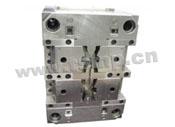
injection moulds qingdao
2011.08.18
injection moulds taizhou,injection moulds yueqing,injection moulds ningbo,injection moulds qingdao,injection moulds guangdong,injection moulds zhejiang,injection moulds shenzhen,injection moulds kunshan,injection moulds jiangsu,injection moulds india,injection moulds USA,injection moulds Japan,injection moulds fujian,injection moulds beijing,injection moulds Koras,injection moulds Taiwan,injection mouldsyuyao,injection moulds xiangshan,injection moulds ninghai,injection moulds changan,injection mould
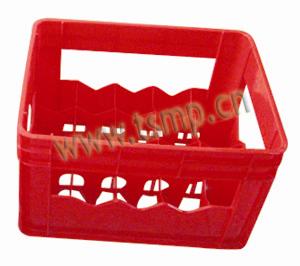
crate molds
2011.08.17
Crate Mould,Bottle Crate Mould,Bottle Crate Mould,Industrial Crate Mould,Vegetable Crate Mould,Fruit Crate Moulds,Fish Crate Moulds,Bread Crate Moulds,Milk Crate Mould
Die moulds and stamps
2011.08.17
TSMP MOULD Is located in Taizhou City Zhejiang province of China. We are middle size of mold maker company and about 40 machines in house. We made about 400 molds last year and 90% molds were exported to Europe, North American and other oversea areas.We are able to make small and simple molds, big and complex molds, we have made some insert molds, overmolds, two shot molds, gas assistant molds, unscrewing molds, hot runner molds and complex molds with many sliders drived by hydraulic cylinder.
Injection Moulding
2011.08.17
TSMP were specialized in manufacturing and developing injection mould (Plasitc mould, Plastic injection mould, Injection manufacturer, Blowing mould and some rotational mould)
Our moulds are widely use in:
1. Daily Necessity goods, including plastic flower pots, baskets, buckets, chairs ect
2. Industry goods, including turnover boxes, double color handle, plastic pails and medical equipment
3. Food packing containers, including microwave wares, storage container, disposable cutlery.
4. Home Appliance mould, including TV, refrigerator, washing machine, air condition ect
5. Automobiles and motorcycle parts
We have at present built steady markets in Italy, U. S. A, Malaysia, Australia, France and so on.
Our moulds enjoy good reputation in the world market for the high quality and competitive price.