NovoTech Machine Tools inc. - Produits, offres, nouvelles
Articles
The Benefits of Using a Rebar Bender and Cutter in Construction
2023.10.01
The Benefits of Using a Rebar Bender and Cutter in Construction
In construction, time and precision are of utmost importance. That's why using a rebar bender and cutter can be a game-changer. Rebar, short for reinforcing bar, is a crucial element in concrete structures. From skyscrapers to bridges, rebar provides the much-needed strength and stability. But manually bending and cutting rebar can be a time-consuming and tedious process. This is where a rebar bender and cutter comes into play.
A rebar bender and cutter is a powerful tool designed specifically for the construction industry. With its ability to effortlessly bend and cut rebar to the required specifications, it eliminates the need for manual labor and reduces project timelines significantly. The benefits of using a rebar bender and cutter are undeniable – increased productivity, improved accuracy, and enhanced worker safety.
Not only does it save time and effort, but it also ensures consistent and precise results, reducing the margin for errors. With the right rebar bender and cutter, construction projects can be completed faster and more efficiently, resulting in improved productivity and cost savings. So, if you're in the construction industry, investing in a rebar bender and cutter is a smart move that can positively impact your business.
Increased efficiency and productivity
One of the primary advantages of using a rebar bender and cutter is the significant increase in efficiency and productivity it brings to construction projects. Manually bending and cutting rebar can be a time-consuming and physically demanding task. With a rebar bender and cutter, the process becomes automated and much faster.
By using a rebar bender and cutter, construction workers can save valuable time that would otherwise be spent on manual labor. This time can then be utilized for other important aspects of the project, ultimately speeding up the construction process. Additionally, the automated nature of the tool ensures consistent and precise results, further improving overall project efficiency.
Enhanced safety and reduced risk of injuries
Safety is a top priority in the construction industry, and using a rebar bender and cutter can significantly contribute to a safer working environment. Manually bending and cutting rebar involves physical exertion and can put workers at risk of injuries such as cuts, strains, and even musculoskeletal disorders.
With a rebar bender and cutter, the need for manual labor is minimized, reducing the risk of accidents and injuries. Construction workers can now operate the tool from a safe distance, eliminating direct contact with the machine. The automation of the bending and cutting process ensures that workers are kept away from potentially dangerous situations, making the construction site a safer place to work.
Precision and accuracy in bending and cutting rebar
Accuracy is crucial in construction projects, especially when it comes to bending and cutting rebar. Any miscalculations or errors can have detrimental effects on the structural integrity of the building. With a rebar bender and cutter, precision and accuracy are guaranteed.
The tool is designed to bend and cut rebar to the required specifications with utmost precision. The measurements can be easily adjusted, ensuring that every piece of rebar is cut and bent to the exact dimensions specified in the construction plans. This level of accuracy eliminates the margin for errors and ensures that the rebar fits perfectly within the concrete structure, enhancing its overall strength and stability.
Cost savings and reduced material waste
Using a rebar bender and cutter can lead to significant cost savings in construction projects. Firstly, the tool reduces the need for manual labor, which means fewer workers are required to complete the bending and cutting tasks. This reduction in labor costs can result in substantial savings for construction companies.
Versatility and flexibility in handling different rebar sizes and shapes
Construction projects often involve working with rebar of various sizes and shapes. Manually bending and cutting different rebar configurations can be a challenging task. However, a rebar bender and cutter offers versatility and flexibility, making it suitable for handling different rebar sizes and shapes.
These tools come with adjustable features that allow construction workers to adapt them to the specific requirements of the project. Whether it's bending rebar into intricate shapes or cutting rebar of varying thicknesses, a rebar bender and cutter can handle the task effortlessly. This versatility ensures that construction projects can be completed with ease, regardless of the complexity of the rebar configurations.
Another crucial factor to consider is the quality and reliability of the tool. Look for reputable brands known for their durability and performance. Investing in a high-quality rebar bender and cutter might cost more upfront, but it will pay off in the long run with its longevity and efficiency.
Lastly, consider the safety features of the tool. Look for features such as safety guards and emergency stop buttons to ensure the well-being of your workers.
Varius types of rebar bending and cutting machines
The market is flooded with various rebar bending and cutting tools, making it essential to choose the right one for your construction projects. Here are a few popular options worth considering:
1. Electric Rebar Bender and Cutter: Electric tools are known for their power and efficiency. They offer precise bending and cutting capabilities, making them suitable for a wide range of projects. These tools are often portable, allowing for easy transportation between construction sites.
2. Hydraulic Rebar Bender and Cutter: Hydraulic tools are known for their strength and versatility. They can handle heavy-duty rebar bending and cutting tasks with ease. These tools are often more expensive but offer superior performance and durability.
3. Manual Rebar Bender and Cutter: Manual tools are a budget-friendly option for smaller construction projects. They require physical effort from the operator but can still deliver accurate results. These tools are lightweight and portable, making them suitable for on-site use.
4. Combination Rebar Bender and Cutter: Combination tools offer the convenience of both bending and cutting capabilities in a single unit. They are versatile and efficient, allowing for seamless transitions between bending and cutting tasks.
Factors to consider when choosing a rebar bender and cutter
When considering the purchase of a rebar bender and cutter, there are several factors that construction professionals should take into account. These factors will help determine which tool is best suited for their specific needs and requirements.
Capacity and Size:
First and foremost, it is essential to consider the capacity of the rebar bender and cutter. Different tools have different maximum bending and cutting capacities, so it is crucial to choose one that can handle the rebar sizes and shapes commonly used in the construction projects you undertake
Determine the maximum rebar diameter you will be working with. Smaller machines suitable for residential and small shop use typically handle rebar up to 25mm, while larger industrial-grade machines can handle up to 60mm or more.
Consider the physical dimensions of the machine to ensure it fits comfortably within your workspace.
Power Requirements:
it is important to consider the power source of the tool. Rebar benders and cutters can be powered by electricity, hydraulic systems, or even manual operation. The choice of power source will depend on factors such as the scale of your projects, the availability of power sources on-site, and personal preferences.
Assess the available power supply in your location. Smaller machines often operate on single-phase 110 or 220 volts, making them suitable for residential and smaller commercial settings.
For larger industrial-grade machines designed for rebar shops, you may need a 3-phase power supply with 600 volts, so ensure that your facility can accommodate this power requirement.
Spiral bending attachment
An optional spiral bending attachment for your rebar bender can revolutionize your construction projects. Electric rebar benders are already essential tools for bending rebar with precision, but adding a spiral stirrup attachment brings several advantages to the table.
Enhanced Versatility: With the spiral bending attachment, your rebar bender becomes a multifunctional tool capable of creating intricate spiral stirrups.
Time Efficiency: Speed up your workflow by effortlessly producing spiral stirrups, saving valuable time on the job site.
Customization: Easily tailor your spiral diameter to project requirements, accommodating unique designs and specifications.
Improved Reinforcement: Spiral stirrups provide enhanced reinforcement for concrete structures, increasing their longevity.
Competitive Advantage: Stay ahead in the competitive construction industry by offering spiral bending capabilities, attracting more clients and projects.
stirrup bending attachment
Adding an optional square stirrup bending attachment to your rebar bending machine can be a game-changer. This innovative tool streamlines production by stacking and bending stirrups simultaneously, boosting efficiency.
Rebar benders equipped with this attachment become versatile rebar bending tools, saving time and labor while ensuring precision in rebar bends. Invest in a rebar bending machine with a square stirrup bending attachment for increased production speed and improved performance in the construction industry.
programmable bending angle
Incorporating a programmable bending angle system with a PLC (Programmable Logic Controller) into rebar benders marks a significant leap forward in manufacturing efficiency. This cutting-edge technology allows for swift production of intricate stirrups and complex forms with remarkable benefits:
Precision and Consistency: The PLC system ensures precise and consistent bending angles, eliminating human errors and guaranteeing top-notch quality in every rebar bend.
Enhanced Speed: Speed up production significantly by programming up to three different bending angles and setting the quantity and sequence for each bend. This reduces downtime and boosts output.
Automation: Gone are the days of manually adjusting bending angles after each bend. With the PLC system, you can automate the entire process by simply pressing a pedal, saving both time and energy.
Reduced Labor Costs: Minimize labor requirements as the system handles repetitive tasks, freeing up workers for more complex and skilled operations.
Customization: Adapt to varying project needs effortlessly by programming different bending angles, providing flexibility in design and construction.
Error Prevention: Human fatigue and errors are mitigated, ensuring that each rebar is bent precisely to specifications.
Time Efficiency: Save valuable time on the job site, allowing for quicker project completion and faster turnaround times.
Increased Output: Boost manufacturing capacity with streamlined processes, meeting project demands more efficiently.
Cost-Effective: The initial investment in a PLC-based system pays off quickly with improved productivity and reduced labor costs.
Incorporating a programmable bending angle system using PLC technology in rebar benders not only expedites production but also elevates the overall quality of construction work, making it a crucial asset for modern construction businesses.
Adjustable bending angles
The advantages of having a rebar bending machine with easily adjustable bending angles and the capability to save up to three different angles in its PLC (Programmable Logic Controller) are substantial and transformative for various industries. Here's a closer look at these benefits:
Time and Labor Savings: Traditional manual angle adjustments can be time-consuming and require extensive labor. With a machine featuring angle presets, operators can swiftly switch between different bending angles with the push of a button, significantly reducing downtime and labor costs.
Error Reduction: Automation minimizes the risk of human error during angle adjustments, resulting in consistently accurate and uniform rebar bends. This enhanced precision contributes to higher quality work.
Increased Productivity: Rapid angle changes and the ability to save multiple presets boost overall productivity. Operators can efficiently switch between various bending requirements, speeding up project completion and reducing bottlenecks.
Auto Mode Convenience: In auto mode, the machine can automatically change the bending angle and sequence according to programmed parameters. This feature simplifies complex bending tasks and enhances workflow efficiency.
Consistency in Complex Bends: For projects involving intricate or multi-step bends, automatic angle adjustments in auto mode guarantee consistent and flawless results, even for complex rebar shapes.
Adaptability to Different Projects: With the capacity to save and switch between up to three different bending angles, the machine becomes highly adaptable to varying project demands, accommodating a broader range of construction and metalworking tasks.
Reduced Material Waste: Accurate angle adjustments mean less material waste due to errors or misalignments, saving resources and reducing costs.
Stack bending and cutting
Stack bending and stack cutting with rebar benders and cutters offer a range of significant advantages for construction and metalworking operations:
Enhanced Efficiency: Stack bending allows multiple rebar pieces to be bent simultaneously, saving considerable time and streamlining the bending process. Similarly, stack cutting enables the simultaneous cutting of multiple rebars, further increasing efficiency.
High Precision: GMS rebar benders and cutters are known for their precision. When used in stack operations, they maintain the accuracy and consistency of bends and cuts across all rebars in the stack, ensuring uniformity in the final product.
Reduced Labor Costs: By automating and expediting the bending and cutting processes, stack operations significantly reduce the need for manual labor, ultimately leading to cost savings.
Minimized Material Waste: Stack operations minimize material waste, as the precision of GMS machines ensures that rebars are cut and bent precisely to the required lengths and angles, reducing scrap.
Increased Productivity: With the ability to process multiple rebars at once, GMS rebar benders and cutters significantly increase overall productivity, enabling faster project completion.
Competitive Edge: Utilizing stack bending and cutting can make your business more competitive in the construction and metalworking industries by offering faster turnaround times and higher precision.
Check for J Hook Tooling:
verify that your rebar bender includes J hook tooling. J hook tooling is specially designed to create the curved shape required for J hooks. This tooling typically consists of a bending die or form that precisely molds the rebar into the desired J hook configuration. Ensure that the tooling is compatible with the rebar sizes commonly used in your projects.
Hardened toolings and parts
Utilizing hardened toolings and parts in your rebar bender offers several crucial advantages.
Durability and reliability are also vital considerations when choosing a rebar bender and cutter. Construction sites can be harsh environments, so it is essential to invest in a tool that can withstand the rigors of daily use. Look for tools made from high-quality materials and with a track record of reliability. It may also be worth considering the availability of spare parts and service support to ensure the longevity of your investment.
Enhanced Durability: Hardened materials resist wear and tear, ensuring a longer lifespan for your rebar bending machine.
Minimized Deformation: Hardened components maintain their structural integrity, preventing deformations that can occur with non-hardened materials.
Reduced Breakage: The added toughness of hardened toolings and plates reduces the risk of breakage during heavy-duty bending tasks.
Consistent Performance: These materials maintain precision and consistency in bending, vital for producing accurate rebar shapes.
Cost-Efficiency: While the initial investment may be higher, the extended longevity of your machine translates into long-term cost savings and improved productivity.
CSA codes compliance:
Ensuring that every machine undergoes inspection by a CSA authorized inspection company and is affixed with a CSA label is crucial for operator safety and the prevention of electrical hazards.
Stringent Safety Standards: CSA codes ensure that machines meet rigorous safety criteria, reducing the risk of accidents and electrical hazards in the workplace.
Operator Protection: Certification guarantees that operators are working with equipment that has undergone thorough inspection, promoting their safety and well-being.
Electrocution Prevention: CSA labeling assures that electrical components are compliant with safety regulations, greatly minimizing the chance of electric shock incidents.
Peace of Mind: Knowing that machines adhere to CSA standards instills confidence in both operators and employers, fostering a secure work environment.
Legal Compliance: Adherence to CSA codes is often a legal requirement, and non-compliance can lead to costly penalties. Ensuring machines are labeled accordingly is crucial for regulatory compliance and risk mitigation.
Well known electrical components
Incorporating renowned European electrical components like Siemens, Schneider, Eaton and ABB into the electric panel of a rebar bender and cutter machine brings a multitude of benefits:
Reliability: European brands like Siemens, Schneider, Eaton and ABB are synonymous with reliability and quality, ensuring that the electrical system operates smoothly and consistently.
Advanced Technology: These brands often incorporate cutting-edge technology, enhancing the efficiency and performance of the machine's electric panel.
Safety: European components are known for their stringent safety standards, minimizing the risk of electrical faults and ensuring operator safety.
Longevity: These brands offer durable components that are built to withstand harsh industrial environments, resulting in longer equipment lifespan and reduced downtime.
Global Support: With a worldwide presence, these brands provide comprehensive customer support and readily available replacement parts, minimizing maintenance hassles.
Motor and gearbox
GMS rebar benders come with a heavy-duty industrial-grade motor directly coupled to a robust planetary gearbox.
As for the motor and gearbox, opting for heavy-duty industrial-grade components in a rebar bending and cutting machine offers several advantages:
Enhanced Durability: Industrial-grade motors and gearboxes are designed to withstand high-stress and continuous operation, ensuring a longer lifespan for the machine.
Consistent Performance: These components deliver consistent and reliable performance, crucial for precise rebar bending and cutting operations.
Increased Productivity: Heavy-duty motors and gearboxes can handle demanding workloads, leading to improved productivity and faster project completion.
Reduced Maintenance: Their robust construction minimizes the need for frequent maintenance and repairs, reducing downtime and costs.
Motor overload protection systems
The incorporation of motor overload protection systems, such as thermal overload relays or variable frequency inverter drives, in rebar benders offers a range of significant benefits, safeguarding both the machine and its operators:
Prevention of Damage: Motor overload protection systems are designed to detect and respond to excessive electrical current or temperature rises in the motor. When triggered, they interrupt power to the motor, preventing damage caused by overheating or excessive stress on the machinery.
Enhanced Machine Longevity: By preventing the motor from running under stressful conditions, these systems extend the lifespan of the rebar bender, reducing the need for costly repairs or replacements.
Operator Safety: Overload protection systems prioritize operator safety. They help prevent overheating of the motor, which can lead to catastrophic failures, potentially causing accidents and injuries to the operators.
Minimized Downtime: Unplanned downtime due to motor failures can be costly and disruptive to project timelines. Motor overload protection systems minimize this risk by proactively addressing potential issues.
Efficiency Optimization: Variable frequency inverter drives offer the additional advantage of optimizing motor speed and power consumption based on the required workload. This not only conserves energy but also reduces wear and tear on the machine.
Customizable Settings: These systems often allow for customizable settings to match specific operating conditions, ensuring that the motor protection mechanisms are finely tuned to the machine's requirements.
Peace of Mind: Operators can work with confidence, knowing that the machine is equipped with safeguards that reduce the risk of motor failure and associated hazards.
Compliance with Regulations: In Canada , motor overload protection systems are required by safety regulations and CSA codes. Compliance ensures that your operations meet legal requirements and minimizes liability.
Cost Savings: The investment in motor overload protection systems pays off in the long run by reducing maintenance costs, preventing equipment damage, and avoiding potential legal expenses resulting from accidents.
In summary, the implementation of motor overload protection systems in rebar benders is a crucial safety measure that not only safeguards machinery but also protects the well-being of operators. These systems contribute to increased machine longevity, reduced downtime, and improved efficiency, ultimately benefiting both the bottom line and workplace safety.
Portability
Portability is a significant factor to consider when choosing a rebar bender and cutter, as it directly impacts where and how you can use the machine. Here's a closer look at the differences in portability between single-phase rebar benders for smaller rebars and heavier 3-phase industrial machines for larger rebars:
Portability of Single-Phase Rebar Benders (Up to 25mm or 1"):
Lighter Weight: Single-phase rebar benders designed for smaller rebars are typically lightweight and compact, making them easy to transport and maneuver on job sites.
Maneuverability: These machines can be transported by a single person or a small team and can often fit in the back of a truck or van, allowing for mobility to various job sites.
Job Site Versatility: Their portability makes them suitable for on-site applications, where rebar bending and cutting are required as part of the construction process. They can be brought closer to the work area, reducing material handling efforts.
Portability of 3-Phase Industrial Rebar Benders (Up to 60mm or 2.4"):
Heavier and Bulkier: Industrial rebar benders designed for larger rebars are substantially heavier and bulkier, making them challenging to move manually.
Forklift Requirement: Due to their weight and size, these machines often require heavy equipment, such as forklifts or cranes, for transportation and positioning. They are typically stationary in workshops.
Shop-Centric: These machines are primarily intended for use in rebar shops or manufacturing facilities where large-scale rebar processing is common. Their size and power make them unsuitable for frequent on-site use.
Budget considerations
Budget considerations are a pivotal aspect of the decision-making process when purchasing rebar bending and cutting machines, as they can significantly impact your construction project's overall cost-effectiveness. Here's why budget considerations should not be overlooked:
Cost-Effectiveness: While upfront costs are important, it's essential to evaluate the long-term cost-effectiveness of your investment. A high-quality rebar bender and cutter may have a higher initial price tag but can yield substantial savings over its lifespan by reducing downtime, maintenance costs, and material waste.
Balancing Features: Finding the right balance between features and affordability is key. Assess your specific project needs and opt for a machine that offers the necessary features without unnecessary frills that can drive up the cost.
Quality Matters: Investing in a reputable brand and quality construction is crucial. Lower-priced machines may seem attractive initially, but they may lack the durability and reliability needed for heavy-duty construction tasks, potentially leading to increased maintenance and replacement costs down the line.
Operator Efficiency: Consider how the machine's features can enhance operator efficiency. A more efficient machine can lead to faster project completion, reducing labor costs and improving overall productivity.
Warranty and Support: Investigate the warranty and customer support options offered by the manufacturer. A strong warranty can provide peace of mind and potentially reduce future repair expenses.
Resale Value: Consider the potential resale value of the machine in the future. High-quality rebar benders and cutters from reputable brands tend to retain their value better than lower-quality alternatives.
Conclusion: Investing in a rebar bender and cutter for construction projects
The market is flooded with various rebar bending and cutting tools, each claiming to be the best. However, a few stand out for their quality, performance, and reliability.
GMS Rebar Benders and cutters offer bending from 20mm up to 60mm and a cutting capacity from 24mm up to 60mm. the rebar cutter powered by a hydraulic system, ensuring smooth and precise operations. The benders are powered by heavy duty industrial grade motor and gearbox.
The GMS Rebar Cutter and Bender is known for its durability and ease of use, making it a popular choice among construction professionals.
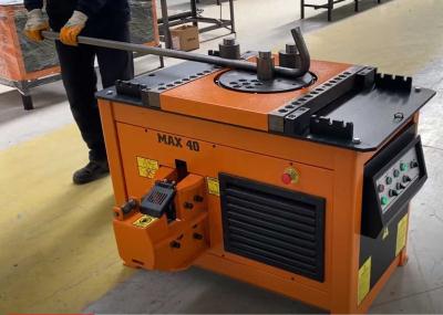
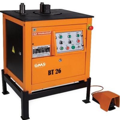
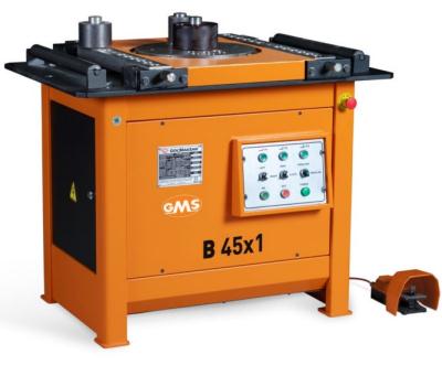
Plate Roller Buying Guide
2023.09.11
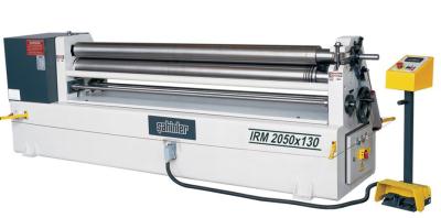
What is a plate rolling machine?
A plate rolling machine is a machine that will roll different kinds of metal sheet into a round or conical shape.
Plate rolls are the ideal machine for metal sheet pre-bending and rolling.
Plate rollers are used to manufacture rounded parts for oil and gas rigs, tunnel supports, boiler equipment, pressure vessels, and heat exchangers among many other things.
A plate bending roll creates a mechanical advantage by pressing a metal sheet between a top roll and two side rolls. The mechanical advantage allows the machine to press the sheet firmly against the rolls, bending it into a conical or spherical shape. Throughout the process, a pinch roll is typically used to hold the metal plate in the correct position.
Plate rolling machines are extremely powerful and able to bend metal sheets of varying thicknesses (typically between 1/16 to 4 inches). Plate rolls come in 3-roll or 4-roll models.
4-roll models could be CNC automated and specifically designed for large-scale, high-volume plate bending needs.
Whilst four roll machines produce fast, accurate bends, three roll machines are ideal for fabricators working with a wide range of material thicknesses and types.
How to choose a right plate roller?
Rolling is similar to forming sheet metal with press brake; it can be a "black art" or maybe magic, but in reality it is neither.
Part of taking roll forming out of the realm of "black magic" is selecting the right sized roller for the job. A good "rule of thumb" for three and four roll machines is that you can roll sheet or plate at 1.5 times the upper roll diameter.
If the top roll has a 10-inch-diameter, the minimum best practice "rollable" inside diameter will be 15 inches.
To determine the proper plate roll sizing, it is critical that yield, tensile strength, width, thickness, and diameter (or radius) of the part are all considered because for example, a higher yield or tighter diameter will require more pressure to form.
Minimum and maximum width is also important because even something as straightforward as material thickness can vary, yet still fall into accepted plate and sheet mill tolerances.
On the application side, you will need to know the minimum and maximum diameter of the cylinders to be formed.
You’ll also need to know if you will be making cones or special shapes as this will determine the correct type and size of plate roll.
Almost all machines achieve precise measurements working at 50% of the full rated value of the roll.
One of the key decision-making factors you should consider is not only what type of plate bender will meet your current needs, but which could also satisfy future business needs.
4 roller plate bending machines
Four-roller machines have a top roll, the pinching roll, and two side rolls. These plate rolling machines produce the fastest and most accurate bends.
The flat metal plate is placed in the machine on either side and "pre-bent" on the same side. The side rolls do the work of bending. The pinching roll holds the plate.
Plate held securely in place between the top and bottom rolls, while the side rolls move vertically to create the bend. Bottom roll moves up to hold the plate surface securely against the top roll while the side roll is raised to form an accurate pre-bend, minimizing the flat zone on the plate edge.
Plate feeding can take place on either side of a four-roll machine. If fed from only one side, they can be placed up against a wall to save floor space.
Side rolls positioned to the right and left of the bottom roll and on their own axes. The independent axis of each roll helps make a perfect bend. The back-side roll (at the far side of the feeding point) also functions as a back-gauge to square the plate for proper alignment which eliminates the need for someone to assist the operator.
Plate is kept square without slipping during both pre-bending and rolling because of the constant secure clamping of top and bottom rolls.
Four-roll machines do not require the operator to remove, flip, and then try to square the plate a second time after pre-bending, (this is not possible in three-roll, initial-pinch machines.)
A cylinder can be rolled to the required diameter immediately following pre-bending because the material can be kept in the machine.
Bending the back edge takes place after the cylinder is rolled allowing for a one-direction, single-pass operation.
For cone-rolling on a four-roll machine, the side rolls can be tilted to establish the cone angle, and the bottom roll also can be tilted to clamp and drive the major end of the cone.
4 roll benders make it possible to create rectangular, elliptical and square-shaped output by carefully bending the metal in specific areas as it passes through the machine.
3 roller double-pinch plate rolling machines
Three-roll, double-pinch machines are available in light to very heavy capacities and do not require the operator to remove, flip, and then try to square the plate a second time after pre-bending, as is the case with three-roll, initial-pinch machines. Cylinders can be rolled to the required diameter immediately following pre-bending because the material can be kept in the machine (this is not possible in three-roll, initial-pinch machines)
Side rolls positioned to the right and left of the top roll and are on the same axis. The axis of each roll helps make the bend. The back-side roll also functions as a back-gauge to square the plate for proper alignment which eliminates the need for someone to assist the operator.
For cone rolling on a three-roll, double-pinch machine, the side rolls can be tilted to establish the cone angle.
Pre-bending on a three-roll plate rolling machine requires that plates be tilted down as they are being fed whereas on a four-roll machine plates are loaded horizontally at the feed level which allows the use of horizontal motorized roller tables to help feed the plate.
3 roller initial-pinch plate bending machines
single-pinch bending machine requires inserting the sheet metal twice to pre-bend both ends. However, there are also double-pinch models available to make pre-bending processes on both ends easier, faster, and more precise.
Single initial-pinch plate rolls are generally only suitable for light-capacity applications. They can be electromechanical or hydraulic and work by pinching the flat sheet between two vertically opposed rolls while the third bending roll moves upward to contact then bend the sheet. These tend to be older machines which in most applications require removal and reinsertion of the sheet to prebend both ends so although cost-effective they are more labor-intensive in a production setting than their modern counterparts.
3 roller variable geometry plate bending machine
The widest range of material types and thickness in relation to the size of the top roll can be rolled on three-roll, variable-geometry machines. They are suitable for medium and thick plate bending.
The three-roll variable pitch works by having all three rolls able to move and tilt. The top roll moves in the vertical plane and the side rolls move on the horizontal plane. When rolling, the top roll presses the metal plate between the two side rolls. The advantage of having the variable three roll is the ability to roll many thicknesses and diameters of cylinders.Three-roller machines have one pressing top roll and two pressing side rolls.
For example; The side-rolls are what produce the mechanical advantage. With the side rolls all the way open, one has the maximum mechanical advantage. With the side rolls all the way in, you have the least mechanical advantage. So, a machine has a capability of rolling 2-inch-thick material with the maximum mechanical advantage, but a job is only 1/2 inch thick. Reduce the mechanical advantage and one has a machine that can roll from 1/2 to 2 inches thick.
The independent axis of each roll helps make a perfect bend. The back-side roll (at the far side of the feeding point) also functions as a back-gauge to square the plate for proper alignment which eliminates the need for someone to assist the operator.
Static pre-bending and Dynamic bending
There are two types of plate bending processes. Static pre-bending is where the metal sheet is held stationary while a roll runs upward along the sheet, bending the leading edge. Dynamic bending, on the other hand, is where the plate or sheet is in motion while running through the machine. The motion of the sheet allows the machine to work more efficiently, thus increasing the sheet bending thickness.
Cone bending
The plate roller can also be used to create a cone shaped piece of metal. In order to do that the metal plate must be cut to the proper size before it is bent. A sheet metal cone can be formed by pre-cutting a flat metal blank with the correct inner and outer radius to form the cone shape wanted. The blank is fed on one side so that the inner radius can be held against a cone rolling attachment. The inner radius is fed through the roller at a slower rate than the outer radius. This process can be a little more difficult and needs to be very exact so cones take a lot of time to fabricate.
Both the three-roll and the four-roll machines are capable of inclining the forming rolls in a positive attitude, and both should have a hardened contrast die to control and slow down the speed of the small diameter.
Guiding the small diameter and inclining the rolls are necessary to roll a cone. In this case you are creating an unnatural situation for the rolling process. Because on a three-roll double pinch machine all three-rolls are driven, it makes it difficult for the contrast die to retard the rotation on the small diameter while making the large diameter move faster.
A four-roll machine which has inclinable forming rolls and a hardened contrast die, will roll cones better than a three-roll.
Controller
Plate rollers can be powered and controlled in multiple ways. Older plate mills are driven by electric motors and newer ones are directed by programs which are loaded into the CNC controller.
DRO: machine comes with Three digital readouts for easy roll positioning as standard accessory. you can set travel limit for each roll on DRO to avoid material over bending by mistake.
NC teach-in controller: In teach-in mode, operator’s all movements are recorded in the controller. In automatic mode all recorded movements are repeated. NC control system has the capacity to save numerous programs. Edit mode allows creating programs manually by inputting rolls position values.
programmable roll bender can improve your capabilities in repeat operations
CNC controller: starting from a menu of standard shapes (cylindrical, oval, polycentric, bucket etc.) and simply entering the shell data (radius, thickness, width, type of material) the control creates the drawing of the workpieces automatically and the complete bending program with all the necessary bending steps. If necessary, the program which theoretically calculated by the controller can be easily optimized by the operator.
Handling and automation options:
Your plate rolling application could require side and overhead supports, automated loading tables and in-feed conveyors, or automatic part ejectors. Don’t forget these important productivity tools when choosing a new plate rolling machine!
overhead supports can prevent light materials from collapsing when rolled to large diameters. A side support can also assist in preventing light materials from recurving toward the floor if the radius is very large.
Rolls crowning
Steel plate rolls–whether they have two or three bottom rolls–all have a top roll. The top roll can be sized to roll plate into cylinders or cylinder segments to radii close to the diameter of the top roll. However, relatively small top rolls can deflect in the center under the pressure of curving steel plate. Alternately, larger-diameter top rolls deflect less but limit the machine to rolling only larger diameters.
Benders and rollers, those who specialize in curving steel plate among other steel products, are asked to roll a variety of plate widths, lengths and thicknesses. Some of the possibilities will cause deflection of the top roll in the rolling process. The result will be the plate cylinder with a barrel form and ends that are not parallel.
With plate rolls that have a long top roll with a small diameter, you will see more deflection. Imagine standing on the middle of a wood beam supported at two ends. As the length on the wood beam gets longer, the deflection where you are standing would sag downwards more. The same concept is applied to steel plate rolling.
To compensate for this deflection in a plate roll, the top roll is “crowned.” A “crown” is the barrel shape of the top roll that is needed to obtain a uniform distribution of the pressure required for the rolling of steel plate. A plate roll has supports at each end and the top roll deflects in the middle when the plate is in motion. This affects the parallelism on the edges of the rolled part.
Insufficient crowning will create an unsatisfactory roll form with barrel effect (where the part has a greater diameter in the middle than at the ends) and hourglass effect (the material is tighter in the middle than on the ends) both possible deformations that can be caused.
Most metal fabricators need a plate roll to work with numerous materials which will affect the plate rolling machine’s rolls in different ways. As a result, rolls are machined with optimal crowning which is typically 75% of nominal capacity if yield, width, diameter, pinch pressure, and speed are equal.
The range of a roll (thickness/width/diameter) depends on the tolerance, with accepted variance of your parts. Options can be installed on the plate rolling machine to adjust for different tolerances and specific crowning can be applied to reach the desired range of material characteristics and part tolerances.
Hardened rolls:
The harder materials and laser/plasma cutting techniques used today require hard outer roll surfaces on rolling equipment. A hardness rating from 50 to 55 Rockwell C scale will have a reasonable penetration depth and provide long-lasting protection against roll surface wear. A hardness rating exceeding 60 will have a shallow penetration and will likely result in cracking or crazing of the roll surface
workpiece finish
Although traditional rollers produce quality, accurate products, they are by no mean polished. If you need a finish free of marks then you’ll have to invest in precision ground rollers which produce a polished finish, but can be more easily damaged. in order to roll aluminum composite, you can choose segmented rolls coated by plastic to avoid scratches on workpiece.
Safety issues:
Most new plate rolling machines are equipped with safety devices such as emergency-stop buttons; safety trip wires; 12-VAC, low-voltage control circuitry; and detached operator control consoles. It is however still your responsibility as the owner to ensure the installation and proper use of these operation safety guards or devices.
Ironworker Machine Buying Guide
2023.09.11
What Is An Ironworker machine?
An ironworker is a compact, multi-functional machine that is considered the workhorse of the Steel Fabricating industry. Often called the swiss-army-knife of machine tools as well.
An ironworker can be an important and versatile machine in a metal fabrication shop. Ironworking is quite often the first step in the manufacturing process, and one ironworker can typically provide enough fabricated material to keep up to seven welders or assemblers busy. These machines generate force using hydraulic systems or mechanical leverage. Modern systems make use of hydraulic rams that are powered by heavy AC electric motors.
Since its invention in the late 1800s, the ironworker’s main strength has been its ability to perform a variety of operations. For example, it can punch a range of materials with punches of various sizes and shapes; it can shear rod, flat bar, angle and channel; it can notch angle iron, pipe, channel and flat bar. That’s not all. Many ironworkers are available with special tooling to bend, stamp and form, too.
The functions of an ironworkers are:
Punching: round holes and oblong holes
Shearing: plate, channel, angle, rod and tube
Notching: plate, angle and tube
Bending: plate
There are numerous models available with different capacities and specifications.
ironworkers have optional accessories that can be added to the stations
How to choose an Ironworker?
As versatile as the ironworker is, it is still possible to purchase the wrong machine – or at least not the best one – for your application. Here are some reasons why careful examination of these factors will prevent that from happening.
Size:
Choosing the right sized Ironworker is more critical than choosing the right brand. While there are many options in sizes each manufacturer will rate their Ironworkers by Tonnage.
When choosing your ironworker there are a few initial questions you need to answer which will help you determine the approximate capacity for your shop:
What is the maximum diameter hole and material thickness you need to punch? This will determine your punching tonnage.
What is the material grade, in PSI, that you will be punching and shearing? Harder materials require more tonnage.
What is the maximum distance from the edge of the material that you need to punch a hole? This will determine the throat depth.
What is the maximum angles size and thickness that you need to shear? This will determine the shearing tonnage required.
What is the maximum width and thickness of the flat bar you need to shear? This will determine the shearing tonnage required.
The principal consideration is the punch tonnage rating. This will determine the maximum hole diameter that can be punched through the maximum material thickness. Just as important is the shearing capacity of plate, angle or flat bar. The shearing tonnage determines the maximum size and thickness of the profile that can be sheared.
Most structural steel fabricating shops require ironworkers in the 80 to 120-ton range, as 120 tons allows for punching a 1-1/4” diameter hole through 1” plate, shearing 6” x 6” x 1/2” angle, and 12” x 1” or 24” x 5/8” plate (55,000 PSI steel).
Typically, a small fabrication shop requires about 60 tons of punching capacity. a 60 ton ironworker will punch a 1-1/16” diameter hole through 5/8”plate depending on tensile strength; will shear 4” x 4” angle, and a 10” x 5/8” flat bar, (55,000 PSI steel). Ornamental iron shops, welding shops and miscellaneous steel fabrication shops often use ironworkers of this capacity. Machines are available up to 192 tons .
Make sure the tonnage / capacity of the Ironworker is right for your application so make sure you look at ALL the manufacturers specifications (not just punching) before you decide the right size / capacity / tonnage ironworker that's right for you.
Beware! Not all tons are created equal. A metric ton actually is heavier than a U.S. ton (2,200 lbs. versus 2,000 lbs.). A machine rated for metric tons should be able to punch a larger hole than a machine rated on the same number of U.S. tons. For example, 80 tons of pressure by U.S. standards can punch a 1" hole through 1" material; 80 metric tons should be able to punch a 1-1/8" hole through the same material thickness.
Be sure to compare the rating of the machine not only in tons, but also the diameter of the hole and thickness of material it can punch. Ironworker tonnage ratings can vary from ironworker to ironworker.
Always allow for headroom above your maximum requirements so you do not work your ironworker at its maximum capacity all day as this will dramatically shorten its life.
Because many different types of steel and ranges of hardness in mild steel exist, it is advisable to get a machine that is at least 20 percent larger than you think your everyday use requires.
When punching hard steel (such as stainless steel) it is better to increase the estimated tonnage by 50 percent, depending on the grade of steel.
Weight
While the weight of a machine tool is not, in and of itself, a critical factor it is an indicator of the rigidity and strength built into the machine. Weight can be increased by several factors but the most common factor would be the frame and ram of the machine. These items, when increased in size add a factor of rigidity and thus longevity to the design.
Capability
Ironworker machines differ in core capabilities without having to purchase a myriad of options. The basic options you will need are punching, shearing plate, shearing angle, shearing rod/bar and notching. These will be tasks that most fabricators will repeat on a daily basis. Other features may be plate bending, tube/bar bending, channel shears, oversized punches, gang punching and many other features. The more capabilities available on your Ironworker the better.
Ironworkers are available with different designs to enhance versatility. For example, the stations on some machines are permanently built in. These machines offer punching stations, angle shears, rod shears, notchers, and short flat bar shears.
If you are a structural steel fabricator, you may prefer these machines because the stations cover the majority of the materials you process and do not require tooling changes.
If you are a general welding, fabrication, maintenance, and structural steel fabricator who does not know what a customer will bring in the door tomorrow, you may want an ironworker that offers the capability to adapt to all customer needs.
Tabletop tooling concepts, which provide a wider variety of tooling, may suit your needs.
In addition to angle shears, rod shears, notchers, and flat bar shears, tabletop ironworkers offer options such as press brake bending attachments, tube shears, channel shears, pipe notchers, V notchers, picket tools, square tube shears, and a variety of special tooling. Although these machines can use a larger variety of tooling than those with built-in stations, time is required to switch from one operation to the next.
Automate
Just like every other machining process today there are a variety of ways your ironworker can be automated. From automatic or programmable backgages to positioning systems for punching , the standard ironworker can be equipped with simple electric back gauge or add-on programmable devices to improve your capabilities in repeat operations, or be purchased with sophisticated CNC controls from the manufacturer.
guillotine, or fixed-rake-angle shear?
All ironworkers are equipped with flat bar shears. The main differences between flat bar shear stations are the length and the approach of the blade to the metal. Some ironworkers use a guillotine, or fixed-rake-angle shear, and others use a scissors-type shear .
The advantage of the fixed-rake-angle shear is that the blade angle remains constant throughout the cut, sometimes offering larger capacity without increasing machine tonnage. The advantage of the scissors-type shear is that it can vary the rake angle of the blade, thereby minimizing distortion.
The advantage of a scissors-type shear is that it can vary the rake angle of the blade. Thicker material is cut closer to the pivot point, and thinner material is cut farther from the pivot point, where the rake angle of the blade is flatter, thereby minimizing distortion. Scissors machines typically have a longer flat bar shear, some up to 24 in. long.
The advantage of the fixed-rake-angle shear is that the angle of the blade as it approaches the work remains constant throughout the cut, sometimes offering larger capacity without increasing machine tonnage. The disadvantage is that without the ability to vary the rake angle, the distortion of the drop piece will remain the same throughout the cut.
On some ironworkers, the rake angle of the bar shear blade is adjusted by inserting and removing wedge-shaped shims above the shear blade. This may require substantial mechanical ability and substantial time. Also, if the shims are not adjusted each time material thickness changes, the machine could be damaged.
Safety Issues
Safety is an important factor when choosing an ironworker.
Examine the guarding. Be sure it can be adjusted down to within 1/4 in. from the top of the material to be punched, and to the bottom of the guard or stripper (this is an ANSI standard). This will prevent operators from placing any part of their bodies between the material being punched and the stripping mechanism.
All other stations should offer complete safeguarding as well.
Beware of machines with automatic urethane hold-downs. Most operators realize the danger of the blade but do not expect to be hurt by safety guards and may not watch them. Automatic urethane hold-downs, if not adjusted properly, also come down with many tons of force and can be dangerous pinch points.
For productivity as well as safety, the machine you choose should offer an infinitely adjustable stroke control to minimize machine movement, decrease the number of pinch points, and increase strokes per minute and production. This is especially important in bending applications and for special tooling for which the upstroke must be adjusted in addition to the downstroke.
Electric stroke controls offer advantages over mechanical linkage controls. Electric stroke controls have quicker cycle times and more precise stopping because they use switches that send signals to the control valve almost instantly. Machines that use mechanical linkage stroke controls must be in motion to cause the linkage to close the control valve. As the valve closes, the machine slows down and is more difficult to regulate.
Safety instructions should include proper alignment of the punch and dies. Because punches are usually hardened to 58 Rockwell, the punch will not bend as it collides with a die. If it is out of alignment, it is more likely to flake or even explode, causing serious harm to the operator.
The preferred and most widely used method of aligning the punch and die is similar to the way punch presses have been aligned for many years. This is done by bringing the punch ram to the bottom of the stroke and installing the punch and dies with the stroke down. This way, the punch already has been entered into the die, the alignment can be checked, and guards may be replaced without machine movement.
Quality
In trying to determine quality, consider the size of the pivot points and beam strength of the steel that is under pressure. Since your ironworker produces many tons of force, the force must be generated and transferred through the pivot points as well as the beam.
Another good indicator of quality is how much shock is produced when the ironworker punches. Excess shock, which can be identified by a loud popping or banging noise as the punch goes through the material, could indicate the beam or side frame is stretching and snapping back into place. Continued shock can cause welds to break, as well as other failures. Higher-quality machines control this by increasing side frame, beam, and pin size.
automatic lubrication unit also can be an indicator of quality. Although all machines have grease points on pivot points and guide assemblies, some machines have an excessive number of grease points as many as 20 or more. Usually these additional grease points have been added in an effort to correct galling problems. It is unrealistic to expect operators to grease more than five or 10 grease points, and machine failure or galling most likely will occur.
Because an ironworker is an important part of most shops, when even one ironworker breaks down, the negative impact on production is significant, even paralyzing. Before purchasing an ironworker, take the time to analyze your needs and carefully assess the quality of the ironworker. It will be time well spent.
Single operator: only one person may operate any of the tool stations at one time.
These types of ironworkers are more prevalent in smaller shops and, in many cases, provide floor space savings over dual operator units.
Dual operator: provide the added capability that more than one worker may operate other stations besides the punching station at the same time. This capability increases the shop’s production capacity and efficiency.
The dual operator capability is achieved by the incorporation of a second cylinder. One cylinder will power the punching station, while the other cylinder will power the other tooling stations.
With the right application these “Dual Operator” machines can be production powerhouses allowing for nonstop punching while all the other features of the ironworker are available for other uses.
Dual operator units are more expensive than single operator units; however, this price difference is quickly erased with the higher productivity achieved.
NovoTech Machine tools is a great resource for Ironworkers and Ironworker accessories and Attachments. We specialize in Fabricating Machinery and can help you select the right attachments and accessories for your application.
How To Use a Hydraulic Ironworker Machine?
Punching
The punch station on Ironworker allows for a wide variety of punching, stamping or embossing applications. The removable table allows for flange or leg down punching of standard channel and angle sections.
Punching Capacities
You can determine the tonnage required to punch A36 mild steel (yield strength 32,300 psi, 65,000 psi tensile) by applying the following formulas for round or shaped holes. For materials other than mild steel please refer to the multiplier table.
Round Holes:
Punch Diameter x Material Thickness x 80 = Tons of pressure required
Example:
How many tons of force do I need to punch a 3/8" hole in ¼" mild steel?
.375 x .25 x 80=7.5 tons
Shaped Holes:
1/3 Punch Perimeter x Material Thickness x 80= Tons of pressure required
Example:
How much force do I need to punch a 3/8" x 1" rectangular hole in ¼" mild steel?
(.33 x 2.75) x .25 x 80=18.2 tons
Material Multiplier
When punching materials other than mild steel first calculate tonnage as shown above then apply the multiplier for the listed material.
Material Multiplier:
Aluminum: 0.38
Brass (1/4 hard): 0.70
Copper (1/2 hard): 0.52
Steel (50% carbon): 1.50
Steel (cold rolled): 1.24
Bar/plate shearing
Ironworker machine will include a bar/plate shear as a standard feature. The bar/plate shear will provide a distortion and burr free shear cut to mild steel bar or plate stock as listed in the Ironworker Specifications. The Shearing Station on Ironworker allows for straight or angled cutting applications. The material hold down adjusts with a simple hand crank to safely restrain the material being cut.
Angle shearing
Ironworker include an angle iron shear as a standard feature. The angle shear will provide a distortion and burr free shear cut to mild steel angle stock . The Angle Shearing Station on Ironworker allows for straight cutting and miter cutting applications. An oversized material hold down adjusts with a simple thumb crank to safely restrain the material being cut.
Angle Mitering
Rod shear / multi-shear tooling
"bump-die" shear tooling is available for Ironworkers. Rod Shear or Multi Shear Tooling will provide distortion and burr free cuts to mild steel rod and square bar stock.
Notcher tooling
Notch tooling will provide a distortion and burr free, three sided shear cut to mild steel bar, plate or angle stock. The Notching Station on Ironworker allows for shaped, straight or angled notch cutting applications.
V-Notch Tooling (OPTIONAL)
Optional V-Notch tooling will provide a distortion and burr free, two-side, 90 degree shear cut to mild steel bar, plate or angle stock. Common use of this tooling is in the fabrication of angel iron frames.
Pipe notch tooling (OPTIONAL)
Optional Pipe-Notch tooling will provide a distortion and burr free notch cut to mild steel pipe stock.
Press brake tooling (OPTIONAL)
Optional Brake tooling is available for your Ironworker. Brake tooling will allow for the graduated bending of flat, bar or angle stock up to 90 degrees.
Electric stroke control (STANDARD)
Electric stroke control is standard on most Ironworker machines. Stroke control enables the Ironworker operator to shorten up and down stroke with minor adjustment of two hand screws. Utilize stroke control to control precision bending with your brake tooling, control stroke when using embossing or bump dies or simply increase production from your punch, notch or shear stations.
Central lubrication unit
Grease your machine minimum of once for every 8 hours of use. This is the most important thing you can do to make your machine last a long time.
Metal Bandsaw Buying Guide
2023.09.11
What is a band saw machine?
A bandsaw is a power saw with a long, sharp blade consisting of a continuous band of toothed metal stretched between two wheels to cut material. They are used principally in woodworking, metalworking, and lumbering, but may cut a variety of materials. Advantages include uniform cutting action as a result of an evenly distributed tooth load. Most bandsaws have two wheels rotating in the same plane, one of which is powered. The blade itself can come in a variety of sizes and tooth pitches (teeth per inch, or TPI), which enables the machine to be highly versatile and able to cut a wide variety of materials including wood, metal and plastic.
Metal cutting bandsaws
Bandsaws dedicated to industrial metal-cutting use, such as for structural steel in fabrication shops and for bar stock in machine shops, are available in vertical and horizontal designs. Typical band speeds range from 65 ft/min to 330 ft/min although specialized bandsaws are built for friction cutting of hard metals and run band speeds of 15,000 ft/min (76 m/s). Metal-cutting are usually equipped with brushes or brush wheels to prevent chips from becoming stuck in between the blade's teeth. Systems which cool the blade with cutting fluid are also common equipment on metal-cutting bandsaws. The coolant washes away swarf and keeps the blade cool and lubricated.
Band saws are classified based on the orientation of the cut.
A vertical bandsaw, also called a contour saw, keeps the blade's path stationary while the workpiece is moved across it. This type of saw can be used to cut out complex shapes and angles and contouring. The part may be fed into the blade manually or with a power assist mechanism. This type of metal-cutting bandsaw is often equipped with a built-in blade welder. This not only allows the operator to repair broken blades or fabricate new blades quickly, but also allows for the blade to be purposely cut, routed through the center of a part, and re-welded in order to make interior cuts. These saws are often fitted with a built-in air blower to cool the blade and to blow chips away from the cut area giving the operator a clear view of the work. This type of saw is also built in a woodworking version. The woodworking type is generally of much lighter construction and does not incorporate a power feed mechanism, coolant, or welder.
Horizontal bandsaws hold the workpiece stationary while the blade swings down through the cut. This configuration is used to cut long materials such as pipe or bar stock to length. Thus, it is an important part of the facilities in most machine shops. Small horizontal bandsaws typically employ a gravity feed alone, retarded to an adjustable degree by a coil spring; on industrial models, the rate of descent is usually controlled by a hydraulic cylinder that bleeds through an adjustable valve. When the saw is set up for a cut, the operator raises the saw, positions the material to be cut underneath the blade, and then turns on the saw. The blade slowly descends into the material, cutting it as the band blade moves. When the cut is complete, a switch is tripped and the saw automatically turns off. Band saws use a continuous saw blade. Chip removal is rapid, because each tooth is a precision cutting tool and accuracy can be held to close tolerances eliminating or minimizing many secondary machining operations.
The horizontal bandsaw is operated hydraulically by controls on a control box, which is located on the front side of the machine. A motor and pump assembly supplies hydraulic fluid from a reservoir in the base to a cylinder, which raises and lowers the support arm and also controls the feed pressure and band tension. A speed and feed chart are sometimes provided on the machine, but when it is not, consult the operator's manual for the proper settings for sawing. More sophisticated versions of this type of saw are partially or entirely automated (via PLC or CNC) for high-volume cutting of machining blanks. Such machines provide a stream of cutting fluid recirculated from a sump, in the same manner that a CNC machining center does. The coolant cools the saw band and also washes away chips from the cut before they can clog the band. Two band guides use rollers to twist the band so that the teeth are in the proper cutting position. The guides are adjustable and should be adjusted so that they are just slightly further apart than the width of the material to be cut. This will give maximum support to the saw band and help assure a straight cut.
What to Look for When Buying A Metal Cutting Bandsaw?
Before you jump straight in and buy, it’s best to think about your needs and requirements. If you can put a list together, this will certainly narrow down the selection of bandsaws available.
What are the Key Features to Look For? Depending on the size of the machine and the tasks you need to perform you may only be looking for one or two of these features, but here is a list of the key ones we think you need to look for…
Size
bandsaws come in sizes ranging from 7”- 80” with model numbers correlating to their max capacity in millimeters when cutting at 90°. E.g. an OSA 300 will fit Ø300 mm round bar stock. Larger capacity saws generally have larger motors providing more torque and allowing the operator to cut faster, not just larger, and to increase the speed at which the blade can get through the material. But as size increases, so do prices. How big is big enough? That all depends.
What size and type of material are you cutting on a day to day basis? We typically recommend getting 1-2” more clearance than your most commonly cut material. This allows you to squeeze in those one-off cuts but keeps you from buying more machine than you need.
Pivot bandsaws (scissor style)
as the name implies, pivot on a bearing on one side of the head, similar to a pair of scissors. In a pivoting scissor head machine, the blade enters the material at an angle and traces the circumference of the material being cut, which results in a longer cutting cycle. The down feed pressure on a pivoting head will be greatest closer to pivot point and will lessen as you get farther away. On structural shapes such as I beam or square tubing, the pivot saw will produce a better cut as the blade wanders less when it enters these materials at the more severe angle provided by the scissor head. Scissor type bandsaws tend to require a smaller investment than their dual column cousins; they are typically a good fit for smaller job shops or as back up or one-off machines for production facilities.
have a pair of large columns, one on either side of the work, for very high rigidity and precision. Dual column machines raise and lower the head on precision ground linear guides. With dual column bandsaws, the blade enters the material at an angle, typically smaller than the scissor style machines, but cuts along the diameter of the material. Dual column saws are much more rigid than their pivoting counterparts due to the dual columns holding both ends of the head, resulting in near constant down feed pressure and feed speed across the entire width of the cut. This rigidity also reduces vibration, resulting in a better cut quality and a longer blade life. Dual column sawblades also take the shortest route through the material, decreasing the time required per cut and increasing production numbers. While dual column machines produce better cuts faster, they also tend to have heavier price tags. However, the increased cost can be quickly recovered by the increase in production numbers. This larger investment usually makes sense for more demanding production lines working with larger materials. For the metalworking industry, the double-column band saw is the most machine type in the band saw inventory.
Manually operated bandsaw machines
Gravity feed saws fall under their own weight. Most such saws have a method to allow the cutting force to be adjusted, such as a movable counterbalancing weight, a coil spring with a screw-thread adjustment, or a hydraulic or pneumatic damper (speed control valve). The latter does not force the blade downwards, but rather simply limits the speed at which the saw can fall, preventing excessive feed on thin or soft parts. This is analogous to door closer hardware whose damping action keeps the door from slamming. Gravity feed designs are common in small saws. Manual bandsaws require the operator to lift the head after each cut.
Compared with hydraulic feed, gravity feed is more cost-effective.
Semi-automatic band saw machines
A semi-automatic saw will make one cut, raise the blade back up out of the material and stop. The material must then be repositioned by the operator in order to make another cut. head movement is controlled by a hydraulic piston, and can be raised and lowered by the operator activating the up/down switch. To run the machine, the operator tightens material in the vice and pushes the Start button. The saw will make the cut, then lift the head back to the upper position. Semi-automatic saws are a good fit if you need to make a few cuts in a length of material.
Fully automatic band saw machines:
An automatic saw will continue to automatically feed material and make cuts according to a specific program, until the job is complete or the saw runs out of material. The automatic band saw has functions of preset feeding rate, returning, falling, part feeding, and clamping. Take advantage of these modern functions in a production environment. Under such machine conditions, if one equipment operator is assigned to each saw, it will not be practical. Modern band saw tasks require that each operator can feed and unload many automatic band saw machines. Due to its CNC controlled function, the automatic band saw not only has faster cutting speed, but also has higher precision. A well-made CNC band saw machine is composed of several key elements, including falling mechanism, feeding mechanism and automatic saw. Some CNC band saws employ a leadscrew and servo motor to feed the saw.
Fully automatic horizontal bandsaw operation is as follows:
1. Material is placed into the roller vice and the vice is tightened
2. The operator sets the desired cut length, typically measured by a limit switch or encoder
3. The number of desired parts is entered into the controller
4. The operator presses the Start button
5. The saw will make the cut and the part will fall out of the back of the machine and into the parts collection bin.
6. The machine raises the head and the material is advanced until the next set length
7. The cycle continues until the numbers of cuts entered into the control is reached
There are three things that will stop a fully automatic saw cycle. The first is completing the job. The second is running out of material. When this happens, most saws will pause and wait for more material to be added, then complete the cycle. The final is if the bandsaw blade breaks. (All saws feature auto blade-breakage detection.)
Fully automatic saws are best suited for production lines which need to cut multiple pieces to the same length.
Feeding mechanism in fully automatic band saw machines:
Shuttle-vice: one of your options for advancing material through a horizontal bandsaw is a shuttle-vice style. Shuttle vices work by the vice head moving away from the saw blade, clamping around the material, and pulling the material forward to be cut. Shuttle vices are the best option when bundle cutting, as they are typically stronger and much accurate than their roller-style counterparts, enabling larger, heavier materials to be moved, and prevent slippage within the bundle.
Powered roller: The standard vice on fully automatic saws tends to be the powered roller style, which holds 3-5 cylinders vertically against each side of the material. One side is grooved, to assist with catching and advancing the material, and the other is smooth, containing a limit switch activated by the pressure of the material inside the vice. Compared with shuttle vice, powered roller is more cost-effective.
Miter or Dual Miter Cutting
Having this ability is what makes bandsaws stand out over powered hacksaws. A lot of processing, especially in the fabrication workshop will need to be angles and therefore miter cutting is a necessity. Not just having miter cutting, but accurate miter cutting with a precise scale. For some fabrication projects, miter cuts will help to give you a more professional product, but when you’re trying to cut corners, mitering is the only way to go. There are assortment of horizontal mitering bandsaws, with options for a swiveling head or a swiveling vice, each combined with either a scissor type or dual column set up and offered in fully or semi-automatic.
Single mitering band saw can cut at an angle (aka to miter) in the positive direction (+30°, +45°, etc.) ; Dual miter cutting is another great feature to have, especially good for workshops that have a multitude of cuts to do on non-symmetrical material.
dual mitering band saw can cut in both the positive AND negative direction (+60°, +45°, +30° -30°, -45°, etc.).
Swiveling head vs. swiveling vice
With a swiveling head the material is fed into the vice perpendicular to the machine base and the entire blade and housing can be moved to set and cut the desired angle. What is the advantage to this? Production lines can be set up with minimal clearance as the material will always move in a straight line. Disadvantages to this? Price. Enabling a saw head to rotate requires a larger, stronger frame. This increases the price of the machine. However, if you are making a lot of unique miter cuts in a shop with limited space, a swiveling head is worth the investment.
A swiveling vice will clamp your material at the angle you wish to cut, requiring additional space around the machine for the material to extend. The saw blade and housing do not rotate, the positioning of the vice (and as such the material in the vice) dictates the angle at which the material is cut. If mitering is something that is not needed on a regular basis and you have the room to move your material, then a swiveling vice is most likely the way to go, as they typically require a smaller investment.
Hydraulic top clamp
The hydraulic top clamp allows the operator to easily, with minimal tack-welding of the ends or strapping, cut multiple pieces of material by applying pressure in 2 directions simultaneously to ensure a clean and complete cut.
Bundle cutting
To get blanks on the floor faster, shops use bandsaws to cut several square, rectangular or round solid bars or tubes at a time. Bandsaws have a fairly large work envelope that allows materials to be stacked and cut. It’s about efficiency and generating a high volume of parts in a short period of time. But if a shop is going to be cutting a high volume of bundles for a specific job, it will need a dedicated bandsaw.
Bundle cutting is generally done with an automatic or semiautomatic dual column or scissor-type bandsaw with V jaws or shuttle vice.
To cut tubing on single- or dual-column horizontal bandsaws—and some vertical ones—the machine needs a canted head, meaning it is mounted at a slight angle, producing the same effect as angling the workpiece. The bandsaw blade passes through the tube at an angle, improving the consistency of the cut and increasing blade life.
With horizontal machines, the blade is offset anywhere from 3 to 5 percent. The blade does not come in perfectly parallel with the material, and this helps eliminate tooth strippage. This is done more for tubing, where you have interrupted cuts.
To minimize movement and vibration, workpieces must be tightly secured. In addition to the side vises already on the bandsaw, the most effective method to hold material in place is to use a top clamp, commonly referred to as a bundle cutting attachment, an option on most production bandsaws. The side vises maintain the position of the material and the top clamp applies down pressure, keeping an individual piece from popping up and out from the bundle.
For bundle cutting, the most effective cuts are those made in solid bars using bi-metal blades. When blades continuously cut solid material, stresses on the teeth after initial impact tend to be consistent. Bundle cutting solid materials is like cutting one big workpiece.
Variable blade Speed
Different materials will require different speeds for optimum cutting. Some machines may come with a belt drive with three or four speeds which are good, but a variable speed is definitely preferable. Not only will this give you easy speed changing, but also great flexibility of use over many materials. With the overall benefit of making your blades last much longer.
Most band saw machines come with variable blade speeds
Swarf auger
If you plan to run your saw continuously a chip conveyor will ensure your chip chute doesn’t overflow, reducing downtime, saving money. The chip auger especially helps to move larger, heavier chips (e.g. cutting iron with a large tooth blade), which might otherwise sink to the bottom of the chute and not be flushed to the coolant collector. Running your saw 8+ hours a day, every day? You need this.
Band tensioning
Bandsaw blades require tension and lots of it to consistently produce straight, uniform cuts, especially in thick or dense stock. Blade “tension” is a technical description of how tight the bandsaw blade is. Bandsaw blades are tensioned by the amount of force per cross-sectional area of the blade, expressed as PSI. Two blades of different sizes will require different forces to achieve the same PSI.
Band tensioner is a closed hydraulic system, manually or hydraulic actuated controls the saw blade tension.
in case of blade breakage; Blade tensioner instantly stops rotation of the saw blade wheel, shuts off the motor drive, and prevents restarting of the motor until a new blade is installed and tension is applied thereto.
Manual blade tensioner: most machines include a manual blade tensioner and gauge to read and set the blade tension manually.
Hydraulic blade tensioner: Temperature change due to friction can change blade length and tension while cutting parts.
you can choose to have hydraulic band tensioner on your machine to Ensures blade is always at optimum tension. by mean of hydraulic cylinder and pressure switch connected to a PLC controller, machine automatically keeps its blade tension constant in cutting process.
Variable pressure Hydraulic vise
Hydraulic vise provides easy setup compare to manual vise.
Some machines have a gauge to check the vise pressure and a valve to adjust it.
If the clamping pressure is adjustable, use the maximum pressure for solid stock and enough pressure to clamp thin walled structural without deforming them.
Sensitive down feed control
The saw fed by a hydraulic cylinder could be regulated by a sensitive feed control valve depending on the material characteristics. The benefits: Higher cutting output, longer blade life, low-vibration cutting, constant chip removal.
Blade slippage sensor:
This sensor detects blade slippage in case blade stuck in the workpiece or blade tension is not enough. in case of band slippage on wheels; sensor instantly shuts off the motor drive to avoid damages to the blade and wheels.
Quick approach sensor
This optical sensor detects workpiece height so blade approaches to workpiece quickly; then decrease feed speed in order to cut material. this feature increase productivity of band saw.
Another option is mechanical workpiece height detector which adjust up lift height of band according to workpiece diameter. this feature avoids blade idle up lift in repeat cut and increases efficiency significantly.
Blade deviation sensor:
Blade deviation sensor and control system is designed to sense and control saw blade deviation. A pair of spaced proximity inductive sensors is positioned adjacent to a side of the saw blade in order to detect blade deviation during operation. controller receives input from each of the pair of sensors in order to control and adjust band tension on the blade and adjust blade force on the work piece.
Hydraulic carbide guide
Hydraulically controlled carbide guides are actuated when the machine’s hydraulic system is started to ensure rigid blade guide clamping for accurate cuts
Infeed Roller Tables and powered Roller Conveyors
Another great accessory especially for the larger workshop are roller stands. When cutting stock, these provide a stable structure that supports the weight of the material, whilst also making it easy to feed it into the vice.
A little push goes a long way! While they cannot initiate movement, the rollers greatly ease material movement.
Motor driven roller conveyors are recommended for use in conjunction with hydraulic top clamps and shuttle vices in fully automatic horizontal bandsaws. Using a small but powerful motor, the tables help the shuttle vice to move heavy materials into position to be cut. The combination of shuttle vice, hydraulic top clamp, and motor driven roller conveyor results in a machine made for mass production with minimal hands-on time.
bundling infeed table helps you stack material easily in order to bundle cutting
Rigid Construction
As with most engineering machinery, solid steel and cast-iron construction are very important. This is so the machine can withstand the cutting forces put on it, as well as giving it vibration dampening qualities that will aid the accuracy of the cut.